 |
LFC - The Palomar Large Format Camera |
| Field Diameter | 24 arcminutes |
| Pixel Scale | 0.18 arcsec/pixel |
| Pixel Size | 15 um |
| Readout time (total mosaic) | 93 seconds |
| Minimum exposure time | 0.6 seconds |
| Gap size between CCDs | ~ 15 arcseconds |
| File size | ~100Mb / mosaic image |
| Data storage format | Compressed Exabyte |
| Imaging devices | 6 x SITe SI-002, 2048 x 4096, thinned, backside illuminated, AR coated |
| LFC Focal Plane Layout:
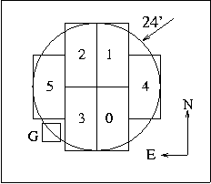
The LFC focal plane holds 6 2k x 4k science grade CCDs, placed in a symmetric cross shaped pattern. The unvignetted f/3.26 beam presented by the Wynne corrector is roughly 24 arcminutes in diameter (see Figure 2). This CCD layout was chosen to minimize the amount of vignetted silicon in the focal plane, and provide a pattern well-suited for tesselation. The CCDs in use are SITe, thinned, backside illuminated devices with AR coating - see the link below for a representative QE curve. A cooled guide CCD is also located in the FP - it is partially vignetted and housed in a corner of the cross shaped pattern of the science CCDs, labeled "G" in Figure 2 (upper right of Figure 1). Upon readout, the mosaic data is stored in 6 separate files, ending with a suffixed number from 0-5. This number maps the file to one of the CCD locations on the focal plane, as indicated in Figure 2. When displaying images from individual chips onscreen, some of the frames will not be shown in the cannonical "North-up East-left" orientation, because of the CCD readout configuration. The table linked below shows the proper sky orientation for each chip as it is displayed onscreen. |

Fig. 1 -Photograph of the LFC focal plane inside dewar. The physical size of the imaging area is about 4" across |

Fig. 2 -Schematic of the focal plane layout, displaying the CCD numbering convention. Large circle shows the illumination pattern of the corrector. |

Two LFC filters mounted in their respective cartridges. The
metal rule
|
LFC Filter Selection:
LFC is equipped with a standard set of Sloan filters (u' g' r' i' z') for public use. Also, C. Steidel has made avalable his custom Rs and Is filters, which are similar to Gunn i and r. At a given time, four filters may be mounted the wheel. Sloan filter transmission curves in digital format: u', g', r',i', z' , or all Sloan convolved with CCD quantum efficiency (.gif format) Private Filters: There are 4 additional LFC sized filters in use with the instrument. Two of these are a pair of narrowband filters owned by R. Ellis, and the other two are custom prescription R and I filters for C. Steidel. Parties interested in the use of these filters should contact their owners directly. Custom Filters: Observers may purchase custom filters for use on the LFC. However, each new filter requires the machining of a new filter cartridge for fitting to the filter wheel. For this reason, interested parties should inquire with the Palomar staff and/or LFC pundits well in advance - i.e. several months before their observing date (or even application for time), in order to provide lead time for machining. LFC filters are quite large - their nominal dimension is 6.1" square x ~5mm thick. Thicknesses up to 10mm can be accomodated, but <6mm is preferred due to weight considerations. |
As of the 2000b semester, LFC has been available for public use. Users who are new to the instrument will need to become familiar with "mcdcom" (the LFC camera control software), and also "lfcguide" (a graphical interface for the guider). Documentation for these programs can be found by following the links shown below.
In addition to mcdcom and lfcguide, many users have found it helpful to use the "mora" display package to look at images as they come off the telescope. Mora (written by M. Metzger) is not considered to be part of the LFC software distribution, but it has been made available to obsevers because it is particularly suited to working with non-square images. Users more comfortable with IRAF / Saotng / ximtool can use these tools for display as well; however, be warned that these were explicitly designed to display output from square CCDs, not 2k x 4k.
Another wrinkle of which IRAF users should be aware: the
default datatype for LFC images is unsigned 16 bit integers (i.e., BITPIX=-16).
This is not a supported IRAF datatype because it is not in the NOST Fits
standard. Therefore, if you want to read data directly into IRAF,
you must set a flag in mcdcom to convert your data to IRAF friendly format
via the introduction of BZERO and BSCALE parameters in the header.
See the manual for details.
| Data Reduction:
Although the need has been expressed by some users for a LFC "pipeline" reduction procedure, there is no such system as yet. However, Matt Hunt has been exploring the possibility of modifying IRAF reduction scripts for KPNO/MOSAIC data to suit LFC output. To date, the modified KPNO pipeline has been able to produce stacked, astrometrically calibrated images of good quality over the central 20 arcminutes of the field. In general, few problems have been reported with the flat fielding properties of the LFC, and the early seps of data processing are smooth. The reduction step which has caused the most problems has been the astrometric calibration of the mosaiced images, due to a sharp increase in optical distortion at field radii > 10 arcminutes. |
 |
Page created by R. Simcoe (ras@astro.caltech.edu) - 2 / 16 / 2001