Fig 1: General Diagram
Fig 1: General Diagram
Detector Controller
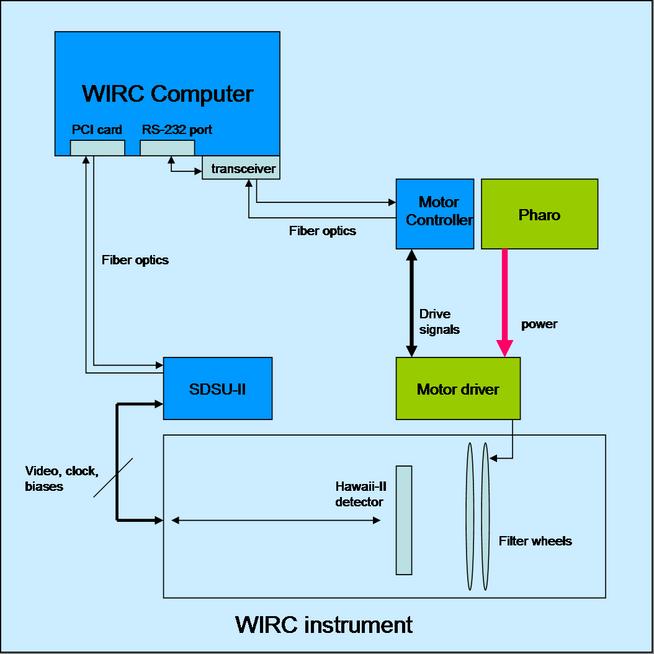
As shown in figure 1, the communications between the Host computer and the controller electronics (SDSU-II controller) is done using a fiber optic link between a PCI card on the computer and the timing board card of the controller. All the image data, and command/response transactions are performed using this two-lines optical fiber (one receiver, one transmitter)
The controller is connected to the detector through
a set of external cables (4 videos, 1 Clock cable, 1 Bias cable)
Motor Controller
As shown in figure 1 and figure 2,
the communication with the motor controller box is done using the RS-485
protocol. The physical media used is fiber optic.
The little gray box on the back of the Host computer is a transceiver
that converts both physical media and protocol. It translates RS-232 to
RS-485, and it goes from a normal electric cable to fiber optic. For this
reason, this box is connected to the RS-232 port of the computer.
At the other side of the fiber optic line, there is another transceiver
which receives RS-485 from the fiber optics and return RS-485 on normal
electrical signals. Inside the motor controller box, then, there are basically
three elements:
- Transceiver fiber-optic To cable (RS-485)
- Two PIC-STEP controllers, one for each filter wheel
The motor controller box is connected with the actual motor driver,
which in turn receives its power from the Pharo box. This motor driver
is connected to the WIRC wheel motors
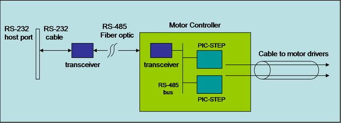
Fig 2: motor controller connections
TCS communications
All the communications with the P200 TCS are done using the network
(RJ-45 ethernet port)