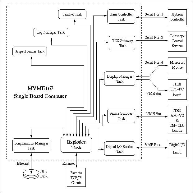

The Exploder task is actually designed to be project independent. Thus on startup it requires a template that describes the contents database, and a list of tasks to be started.
  DbEnum units            - The coordinate units (arcsec
                            or pixel).
  DbEnum sys              - The coordinate system (polar
                            or cartesian).
  char itex[31]           - One of the following ITEX camera
                            configuration names:

       Name         Pixel     Timing   Format  Resolution.
                    clock     source
    DEF_RS512P    10.00 MHz    PLL     RS170    512x482
    DEF_RS640P    12.28 MHz    PLL     RS170    640x482
    DEF_RS752P    14.30 MHz    PLL     RS170    752x482
    DEF_CC512P    10.00 MHz    PLL     CCIR     512x572
    DEF_CC768P    15.00 MHz    PLL     CCIR     768x572
    DEF_CC736P    14.10 MHz    PLL     CCIR     732x572
    DEF_RS512X    10.00 MHz    XTAL    RS170    480x640
    DEF_RS640X    12.28 MHz    XTAL    RS170    640x482
    DEF_RS752X    14.30 MHz    XTAL    RS170    752x482
    DEF_CC512X    10.00 MHz    XTAL    CCIR     512x572
    DEF_CC768X    15.00 MHz    XTAL    CCIR     768x572
    DEF_CC736X    14.10 MHz    XTAL    CCIR     732x572

  float cal_move          - Pixel-calibration move offset (arcsec).
  float cal_mrate         - Pixel-calibration move rate (arcsec/sec).
  float xscale            - The number of arcseconds per pixel along
                            the X axis.
  float yscale            - The number of arcseconds per pixel along
                            the Y axis.
  float phi               - The clockwise image-rotation angle to
                            add to the angle supplied by the TCS.
                            The angle is measured in radians.
  DbEnum east_dir         - The direction of East wrt North
                            (clockwise or anticlockwise).
  DbBool display          - True if the compass should be displayed.
  float x, y              - The normalized position of the compass.
                            0,0 denotes the top/left and 1,1 the
                            bottom/right corner of the display area
  unsigned short length   - The length of the North-south line (pixels).
  char dir[133]           - The directory containing the
                            configuration file.
  char name[133]          - The name of the configuration file.
  DbBool save             - True to save, false to load.
  DbBool done             - Zero to start loading/saving.
DbBool defeat - The line status (true means pause guiding).
  unsigned short width    - The width of the frame.
  unsigned short height   - The height of the frame.
  long intensifier        - Image-intensifier gain from 0% to 100%.
  DbEnum ccd              - The CCD gain (x1, x2, x4 or x10).
  float xscale            - The width of one pixel (arcsec).
  float yscale            - The height of one pixel (arcsec).
  float east_sign         - East wrt North (1=clockwise, -1=anticlockwise).
  float theta             - The clockwise angle of north measured wrt the
                            top of the guider image (radians).
  float sin_t             - sin(theta).
  float cos_t             - cos(theta).
  DbEnum mode             - The grabber mode (frame or field).
  unsigned short exposure - The integration-time in units of 1/30th
                            second.
  unsigned short nstack   - The number of integrated frames to
                            average.
DbBool enable - True to enable the guider.
  DbBool enable           - True to enable the camera and the
                            intensifier.
  float brightness        - The brightness of the display.
  float contrast          - The contrast of the display.
  float mrate             - The telescope move rate when the user uses
                            the goto-button to move the telescope.
  char itex[31]           - One of the following ITEX monitor video
                            format names:

    RS512      -  RS170 512x480 interlaced.
    RS640      -  RS170 640x480 interlaced.
    CC512      -  CCIR  512x512 interlaced.
    CC768      -  CCIR  768x574 interlaced.
    NI640      -        640x480 non-interlaced.
    NI800      -        512x480 non-interlaced.
    NI1K768    -        1024x768 non-interlaced.
    NECNI1K768 -  NEC   1024x768 non-interlaced.
    I1KI1K     -        1024x1024 interlaced.
  float north             - The distance to move North (arcsec).
  float east              - The distance to move East (arcsec).
  float mrate             - The desired move rate.
DbBool initiate - True to initiate, false on completion.
(no members)
  DbBool needed           - True to snap a new frame into the
                            auxiliary frame store, or false to
                            discard.
  long flux               - The flux under the guide-star.
  DbBool usable           - True if x and y are usable.
  float north             - The north offset of the star wrt the
                            center of the target.
  float east              - The east offset of the star wrt the
                            center of the target.
  char msg[133]           - The log message.
  DbBool bad              - True if the message denotes an error.
  DbEnum mode             - What to do with the currently stored
                            frame, (ignore, display or
                            subtract).
  DbBool targetted        - The tracker task sets this to true to
                            notify the tracker task of the arrival of
                            new target area pixels to be processed.
  DbBool targeted         - x and y are only valid when targeted is
                            true.
  unsigned short x        - The horizontal pixel index of the target.
  unsigned short y        - The vertical pixel index of the target.
  unsigned short border   - The number of pixels either side of x,y.
  unsigned short margin   - The width of the background-estimation
                            margin (pixels).
  float tv_angle          - The angle of North, clockwise from the top
                            of the tv (degrees).
  DbBool slewing          - True when the telescope is slewing.
  DbBool ready            - True when the TCS is ready running.
  DbEnum mode             - The tracking mode (guide or drift).
  DbEnum method           - The tracking method (median or centroid).
  float interval          - The minimum time between autoguider move
                            requests (seconds).
  float mrate             - The telescope move rate (arcsec/second).
  float loopgain          - The correction-offset multiplier (0 -> 1).
  float seeing            - The smallest telescope move to command
                            (arcsec).
  float snr               - The threshold signal to noise ratio of
                            included pixels.
  unsigned short x, y     - The top left corner of the viewport.
  unsigned short width    - The width of the viewport.
  unsigned short height   - The height of the viewport.
The Configuration Manager task reads and writes configuration
files. These are text files that describe the contents of database
objects. When an update of the Status object is
received that has the done member of a Status object set
to 0, the configuration manager looks at the
save member to see whether it should load or save objects
from/to the file name specified in the dir and
name members. It then performs the file operation.
This is the task that provides the pixel-size autocalibration
facility. When it receives a Orient object update
in which the initiate member is true, it enters a
state-machine that takes over control of the autoguider. By moving the
telescope in specific directions and watching the resulting guide star
motion across the camera frame, it measures the dimensions and
orientation of the camera pixels wrt the sky. It also determines
whether the image is mirrored. This task is the only task that should
ever write to the Geom object. It keeps this object
up to date with the tv_angle member of the Camera object and the xscale and
yscale members of the Tcs object.
fprintf() called lprintf() (log
printf). This function passes the resulting formatted message to the
log manager task via a custom non-blocking I/O-system device
driver. The log manager then copies the message into a Status object and uses it to update the Status object
in the database.
The TCS gateway is also responsible for forwarding move requests,
received via Move object updates, to the TCS. The
TCS doesn't reply to such messages until the move has completed, at
which point the task resets the fields of the distance and rate fields
of the Move database object to zero. If the TCS
doesn't reply for much longer than the predicted duration of the move,
then the Tcs gateway task sets reports the error and sets the
ready field of the Tcs object to
false. The next time that a move is requested, or if an update of the
Ping object is received, the task attempts to
reestablish a connection with the TCS by sending a GI message.
tvdisp.c and a guider-specific set of functions in
display_manager.c which call on the library to create
widgets and register callbacks.
The widget library implements buttons, sliders, leds, labels, frames etc.. using the fill-rectangle, line drawing and text rendering primitives of the ITEX DM-PC overlay plane. It provides geometry management, event management and many other features that are common to X-window widget libraries. It also reads input from a mouse via a serial line and converts this to motion of the cursor and to mouse callback events.
It would take too long to describe all of the ways that the display manager displays and updates database objects at the user's behest, but there is one behind-the-scenes interaction with the database that deserves a mention. Since the display manager controls the overlay plane and the frame grabber controls the image plane of the tv, the display manager and the frame grabber tasks have to collaborate in setting the size and position of the camera window. This is managed through updates of the View and Frame database objects. There are two events that can cause the size of the viewport to change.
The second case is similar to the first. In this case when the Monitor update is received the current version of the Frame database object is used by the display manager to determine the desired size of the frame grabber, and after reconfiguring the display, the View object is updated to inform the frame grabber of the newly achieved size.
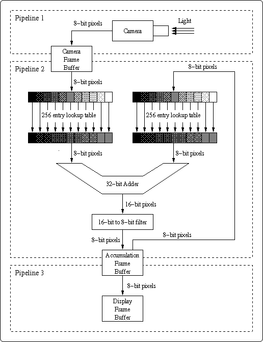
Simplified illustrations of the three main video pipelines are shown in the following diagram.

The camera pipeline is active at all times except when the frame grabber is disabled or when the frame grabber is reconfiguring itself. The camera pixel clock is much slower than the internal clock used for the other pipelines, so each camera frame is accumulated in the camera frame buffer before being pushed through the second video pipeline. Each cycle of the second video pipeline operates during the vertical blank period of the camera, so it can read out of the camera frame buffer before the camera starts to overwrite it. Once the required number of camera frames have been cycled through the second pipeline, the accumulation frame buffer is copied to the image-plane frame buffer of the display.
The frame averaging algorithm, as implemented by the second pipeline, is an 8-bit integer version of:
  for i = 1..n
    mean(i) = mean(i-1) + (intensity(i) - mean(i-1)) / i
This is mathematically identical to an arithmetic mean, but given
limited precision, it preserves low brightness features much better
than the more familiar:
  for i = 1..n
    mean(i) = mean(i-1) + intensity(i) / n
which throws away the bottom log(n)/log(2) bits of every
input frame, and the 8-bit running mean:
  mean(1) = intensity(1)
  for i = 2..infinity
    mean(i) = s.mean(i-1) + (1-s).intensity(i)

  where s = exp(-log(2^8)/n).
which throws away the bottom -log(1-exp(-8.log(2)/n)) /
log(2) bits of each input frame.
The adopted averaging equation requires that the two input frames be scaled down by factors that change from one frame of the sequence to the next. This scaling is performed using 256-entry lookup tables which map input pixel values to appropriately reduced output pixel values. These lookup tables are updated just before each new cycle of pipeline 2 (ie. up to 30 times per second). The box that is labelled 16-bit to 8-bit filter is implemented by a collection of lookup tables and comparison operations that map all 16 bit values that are above 256, to 256, and all values below 0, to 0.
The above diagram only shows the three most important pipelines. In addition there is one that, at the user's request, copies the latest output frame into a spare frame buffer. Another pipeline is responsible for subtracting this from subsequent output frames when frame subtraction has been requested. Finally, a pipeline has to be set up to apply the current grayscale lookup table to the target area. The output of this pipeline is the accumulation frame buffer, after its contents have been safely copied to the display frame buffer. Having filtered the target area, the frame-grabber copies its pixels across the VME backplane for further processing by the Tracker task.
Note that all pipelines except pipeline 1 require the same resources, so each pipeline has to be set up and torn down every frame cycle.
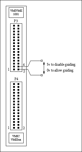
defeat member of the Defeat object to
true if 5v is currently applied, or false if the input is floating or
set to 0 volts. The rational for the guide-defeat line is that it was
predicted that future instruments might want to turn off the guider at
critical moments. The pinout of the front-panel connector is
illustrated in the following diagram of the front panel.
