The kupol receiver has two backends, the universal backend (UBE), which samples the full bandwidth of the receiver (13.5 to 17.2GHz), and provides LCP, RCP and total power outputs, and an FPGA based digital backend that splits the bandpass into 6 bands.
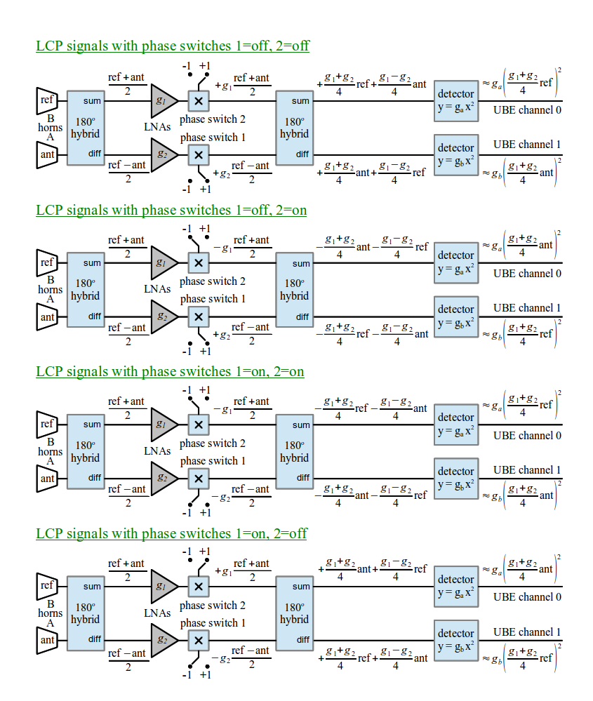
Following the signals from left to right, the ANT and REF signals go to the inputs of a 180-degree hybrid-coupler. The two outputs of this coupler are half the sum and half the difference of the ANT and REF input signals. Igoring the phase-switches for the moment, these sum and difference outputs are passed through a pair of low-noise amplifiers of similar gains. The amplified ANT and REF signals are then recovered from the sum and difference signals by a second 180 degree hybrid-coupler. By this point the recovered signals have both been amplified by the sum of the gains of the two low-noise amplifiers, so any drift in the gain of either amplifier affects both signals equally.
The outputs of the second hybrid-coupler are not purely ANT and REF. The ANT output is contaminated by the REF signal scaled by the difference between the gains of the two amplifiers. Similarly the REF output is contaminated to the same degree by the ANT signal. To make this contamination insignificant, the difference between the amplifier gains must be kept much less than the sum of the gains.
The ANT and REF outputs of the second hybrid each go to different square-law detectors. The outputs of these detectors are proportional to the power of the amplified ANT and REF signals. In the universal backend, each of the these outputs goes to an integrator, followed by a sample-and-hold circuit, and finally an analog to digital converter. Since the two outputs traverse different analog paths between the final hybrid and the analog to digital converter, they are affected by slightly different gains and DC-offsets. This makes the raw difference between the digitized ANT and REF samples a poor estimate of the difference between the signals received by the ANT and REF horns.
The effects of the mismatched analog signal paths can be greatly reduced by periodically alternating the ANT and REF signals between the two signal paths, summing samples of ANT from each of the two signal paths, to get an ANT signal that is affected by the sum of the gains and the sum of the offsets of the two signal paths, and doing the same for the REF signal. Differencing these ANT and REF sums then largely cancels out the unbalanced gains and offsets, leaving a much better estimate of the true difference between the signals that entered the ANT and REF horns. This works well provided that the rate at which the signals are alternated between the two signal paths is significantly greater than the rate at which the gains and offsets of the two signal paths vary.
The job of alternating the ANT and REF signals between the two analog signal paths is accomplished by a pair of 180-degree phase switches situated between the two 180-degree hybrid couplers. When these are both in the same state, the sum and difference outputs of the final hybrid coupler are ANT and REF respectively, whereas when the switches are in opposing states, the outputs become REF and ANT respectively. The following table lists the 4 possible combinations of phase-switch states in the order that the universal backend steps through them during each phase-switch cycle. For each state the corresponding signals that emerge from the 4 receiver output channels are shown.
| Phase Switch | UBE Channel Signals | ||||
|---|---|---|---|---|---|
| 2 | 1 | 0 | 1 | 2 | 3 |
| off | off | ref L | ant L | ref R | ant R |
| off | on | ant L | ref L | ant R | ref R |
| on | on | ref L | ant L | ref R | ant R |
| on | off | ant L | ref L | ant R | ref R |
The universal backend can only transfer one digitized sample to the 40m control computer per millisecond. The kupol receiver has 4 channels that are simultaneously integrated and later digitized, and it takes 4ms to transfer the resulting samples to the computer. While the result of one integration is being transfered to the computer, the next integration is accumulated. Thus the 4ms transfer time also dictates an integration time of 4ms. The states of the phase switches are set by control bits sent by the computer to the universal backend every millisecond. The states of these bits are changed at the start of each integration, then held in the same states for the next 4ms. There are 4 possible pairs of phase-switch states, so it takes four 4ms integration periods to cycle through all of the states. During this time 16 samples are transfered to the computer. Starting from the beginning of a phase-switch cycle, the following table shows the samples that are received from the universal backend during one phase-switch cycle and the corresponding states of the phase switches.
| Downlink Sample | Integration | Phase Switch | Signal | |
|---|---|---|---|---|
| 2 | 1 | |||
| 0 | 0 | off | off | ref L |
| 1 | 0 | off | off | ant L |
| 2 | 0 | off | off | ref R |
| 3 | 0 | off | off | ant R |
| 4 | 1 | off | on | ant L |
| 5 | 1 | off | on | ref L |
| 6 | 1 | off | on | ant R |
| 7 | 1 | off | on | ref R |
| 8 | 2 | on | on | ref L |
| 9 | 2 | on | on | ant L |
| 10 | 2 | on | on | ref R |
| 11 | 2 | on | on | ant R |
| 12 | 3 | on | off | ant L |
| 13 | 3 | on | off | ref L |
| 14 | 3 | on | off | ant R |
| 15 | 3 | on | off | ref R |
The raw samples that are received from the backend are made available
via the ukupol.rx.sample_values[] archive/monitoring
register. This contains up to 1001 samples that are received from the
backend each second. The actual number in each 1 second archive frame
is indicated by the value of the
integer ukupol.rx.nsample register. The times at which
each of these samples were received are recorded in
the ukupol.rx.sample_times[] register, and the origin of
each sample is encoded in the corresponding element of
the ukupol.rx.sample_origins[] register.
After each completed 16ms phase-switch cycle, the control computer
takes the mean of the 4 samples of each of the 4 desired signals, to
compute phase-switch demodulated signals. The phase-switch demodulated
samples of the ANT LCP signal are recorded in
the ukupol.rx.demod_ant_ll[] register. Similarly those of
the ANT RCP, REF LCP and REF RCP signals are recorded in
the ukupol.rx.demod_ant_rr[],
ukupol.rx.demod_ref_ll[],
and ukupol.rx.demod_ref_rr[] registers,
respectively. These are array registers that hold up to 63 demodulated
16ms samples each (1 second/16ms = 62.5 demodulated samples per
second). The corresponding timestamps, which are recorded in
the ukupol.rx.demod_times[] register, indicate the
central times of each 16ms integration interval. The actual number of
demodulated integrations that are recorded in the above registers, is
indicated by the integer value of the ukupol.rx.ndemod
register.
A useful value to be able to plot and use for data analysis, is the
mean of all of the demodulated samples of a given signal during the 1
second duration of an archive frame. Similarly, the sum of the mean
LCP and RCP demodulated samples gives the mean value of the total
intensity (I polarization). The mean values of the ANT RCP samples are
recorded in the ukupol.mean_ant_rr register, those of ANT
LCP in ukupol.mean_ant_ll, and the sum of these, which is
the mean total intensity from the antenna horn, is recorded in
the ukupol.mean_ant_i. Similar registers exist for the
signals from the reference horn. The mean differences between the
demodulated ANT and REF samples are also recorded for LCP, RCP and
total intensity, in
the ukupol.mean_diff_rr, ukupol.mean_diff_ll,
ukupol.mean_diff_i registers, respectively.
The kupol receiver has two noise diodes in the ANT signal path and two in the REF signal path. Of the two diodes in each of these signal paths, the one that is refered to as the "cal" diode is a weak source of noise (~ 3K), whereas the one that is refered to as the "noise" diode is a strong source of noise (~ 30K). Commands are described below that turn these diodes on and off individually. All commands to change the states of these noise diodes are delayed until the start of a new phase switch cycle.
tell
command. Beware that the contents of these strings are not checked by
the script parser when scheduling scripts are parsed, but rather by
the receiver controller when they are actually sent to it.
set command. For example, the following command turns off
the calibration signal for the antenna horn, and sets an attenuation
of 4dB.
tell ukupol, "ant_cal=off, atten=4"Note that this command set 3 different parameters. Other parameters that are not changed by a given
set command, are left
unchanged.
The following is a list of the parameters that can be assigned, along
with the values that can be assigned to them, via the set
command:
ant_cal
ant_cal=on
ant_cal=off
ref_cal
ref_cal=on
ref_cal=off
ant_noise
ant_noise=on
ant_noise=off
ref_noise
ref_noise=on
ref_noise=off
atten
atten=n
time_nfit
time_nfit=n
time_nfit=0
board.name[dimension] DescriptionNote that to select one of these registers in telviewer, read_registers etc, it is necessary to prefix the names shown in this web page with: "
ukupol."
Also note that the two right-most columns of the tables of registers,
show the raw units used to record the values as integers in the
archive files, followed by the floating point units that result after
scaling and offsetting these values by the numbers in
the ukupol.cal instrumental calibration file.
| Register name | Description | Raw units | Cal units |
|---|---|---|---|
frame.record |
The sequential record number. | count | count |
frame.utc[0-1] |
The date and time of the frame, expressed as two elements containing MJD days and milli-seconds, respectively. This register is sought by telcontrol in the register maps of all client systems, and the time that it contains, rounded down to an integer number of seconds, is used to match simultaneous frames from the different systems. | days, ms | days, ms |
frame.utc_status |
The usability of the timestamp contained in the frame.utc register, expressed as a FrameUtcStatus enumerator. | code | code |
| Register name | Description | Raw units | Cal units | ||||||||||||||||||||||
|---|---|---|---|---|---|---|---|---|---|---|---|---|---|---|---|---|---|---|---|---|---|---|---|---|---|
rx.utc[0-1] |
The time of the 1-second tick at which the following information was archived, expressed in MJD days and milliseconds (rounded down to the start of the second). | days, ms | days, ms | ||||||||||||||||||||||
rx.utc_status |
The usability of the timestamp contained in the above utc register, expressed as a FrameUtcStatus enumerator. | code | code | ||||||||||||||||||||||
rx.noise_temp[0-1] |
The temperatures of noise diodes 1 and 2. | milli Kelvin | Kelvin | ||||||||||||||||||||||
rx.temp_10k |
The temperature of the 10K plate. | milli Kelvin | Kelvin | ||||||||||||||||||||||
rx.hybrid_temp |
The temperature of the first 180-degree hybrid-coupler. | milli Kelvin | Kelvin | ||||||||||||||||||||||
rx.plate_temp |
The temperature of the cold plate (nominally 20C). | milli Celsius | Celsius | ||||||||||||||||||||||
rx.rx_temp |
The temperature of the receiver support structure. | milli Celsius | Celsius | ||||||||||||||||||||||
rx.pos_5v_v |
The voltage of the +5V supply. | milli volts | Volts | ||||||||||||||||||||||
rx.pos_5v_i |
The current from the +5V supply. | milli Amps | Amps | ||||||||||||||||||||||
rx.neg_5v_v |
The voltage of the -5V supply. | milli volts | Volts | ||||||||||||||||||||||
rx.neg_5v_i |
The current from the -5V supply. | milli Amps | Amps | ||||||||||||||||||||||
rx.pos_15v_v[0-1] |
The voltages of the stage 1 and 2 +15V power-supplies. | milli volts | Volts | ||||||||||||||||||||||
rx.pos_15v_i[0-1] |
The currents being drawn from the stage 1 and 2 +15V power-supplies. | milli Amps | Amps | ||||||||||||||||||||||
rx.pos_28v_v |
The voltage of the +28V supply. | milli volts | Volts | ||||||||||||||||||||||
rx.pos_28v_i |
The current from the +28V supply. | milli Amps | Amps | ||||||||||||||||||||||
rx.rf_power[0-3] |
The RF powers of the 4 receiver channels. | mV/8.5 (legacy) | Volts | ||||||||||||||||||||||
rx.motor_speed |
The speed of the refrigerator motor (units unknown). | uV | Volts | ||||||||||||||||||||||
rx.hotload_temp |
The hot-load temperature. | milli Kelvin | Kelvin | ||||||||||||||||||||||
rx.backend_temp |
The backend temperature. | milli Celsius | Celsius | ||||||||||||||||||||||
rx.heat_cool |
This indicates whether the backend is being cooled (-5v), heated (+5v) or left at the current temperature (0v). | milli volts | Volts | ||||||||||||||||||||||
rx.flags |
A bitwise OR of the following configuration bits. Note that bit 0 is
the least-significant bit.
Note that for C programs the values of the above bits are
enumerated by the |
bits | bits | ||||||||||||||||||||||
rx.atten |
The setting of the attenuator (0 to 31) in dB. | dB | dB | ||||||||||||||||||||||
rx.nsample |
The number of downlink samples, sample timestamps and sample
origins in the rx.sample_values[],
rx.sample_times[]
and rx.sample_origins[] registers. Since the
1KHz sampling clock in the universal backend is not phase-locked
to GPS, this may be fewer than 1000 samples, or up to 1001
samples.
|
count | count | ||||||||||||||||||||||
rx.sample_times[0-1000] |
The times at which each of the 1KHz downlink samples were received
by the control computer, expressed as a microsecond offset from
the time-stamp in the rx.utc register.
|
micro seconds | seconds | ||||||||||||||||||||||
rx.sample_values[0-1000] |
The raw 1KHz downlinked ADC counts that were received at the times
specified in the rx.sample_times register.
|
ADC counts | ADC counts | ||||||||||||||||||||||
rx.sample_origins[0-1000] |
The origin of each sample in the rx.sample_values[]
register, expressed as an unsigned integer in the bits are
partitioned as follows:
|
bits | bits | ||||||||||||||||||||||
rx.ndemod |
The number of phase-switch demodulated samples and associated
values in the rx.demod_times[],
rx.demod_rr_ant[],
rx.demod_ll_ant[],
rx.demod_rr_ref[],
rx.demod_ll_ref[], registers. This may be
between 61 and 63, because the average number of 16ms demodulated
samples within the 1000ms duration of an archive frame is 62.5.
|
count | count | ||||||||||||||||||||||
rx.demod_times[0-62] |
The central times of the 16ms intervals that were used to
integrate each of the demodulated samples, expressed as a signed
microsecond offset from the absolute time in
the frame.utc register.
|
micro-seconds | Seconds | ||||||||||||||||||||||
rx.demod_ant_ll[0-62] |
The phase-switch demodulated samples of the left-circular polarized signal received by the ANT horn. | ADC counts | ADC counts | ||||||||||||||||||||||
rx.demod_ant_rr[0-62] |
The phase-switch demodulated samples of the right-circular polarized signal received by the ANT horn. | ADC counts | ADC counts | ||||||||||||||||||||||
rx.demod_ref_ll[0-62] |
The phase-switch demodulated samples of the left-circular polarized signal received by the REF horn. | ADC counts | ADC counts | ||||||||||||||||||||||
rx.demod_ref_rr[0-62] |
The phase-switch demodulated samples of the right-circular polarized signal received by the REF horn. | ADC counts | ADC counts | ||||||||||||||||||||||
rx.mean_ant_ll |
The mean of the phase-switch demodulated samples of the ANT LCP
signal. This is the mean of the values in
the rx.demod_ant_ll[] register.
|
ADC milli-counts | ADC counts | ||||||||||||||||||||||
rx.mean_ant_rr |
The mean of the phase-switch demodulated samples of the ANT RCP
signal. This is the mean of the values in
the rx.demod_ant_rr[] register.
|
ADC milli-counts | ADC counts | ||||||||||||||||||||||
rx.mean_ant_i |
The mean phase-switch demodulated total intensity signal from the
ANT horn. This is the sum of the mean of the values in
the rx.demod_ant_ll[] register and the mean of the
values in the rx.demod_ant_rr[] register.
|
ADC milli-counts | ADC counts | ||||||||||||||||||||||
rx.mean_ref_ll |
The mean of the phase-switch demodulated samples of the REF LCP
signal. This is the mean of the values in
the rx.demod_ref_ll[] register.
|
ADC milli-counts | ADC counts | ||||||||||||||||||||||
rx.mean_ref_rr |
The mean of the phase-switch demodulated samples of the REF RCP
signal. This is the mean of the values in
the rx.demod_ref_rr[] register.
|
ADC milli-counts | ADC counts | ||||||||||||||||||||||
rx.mean_ref_i |
The mean phase-switch demodulated total intensity signal from the
REF horn. This is the sum of the mean of the values in
the rx.demod_ref_ll[] register and the mean of the
values in the rx.demod_ref_rr[] register.
|
ADC milli-counts | ADC counts | ||||||||||||||||||||||
rx.mean_diff_ll |
The mean of the difference between the phase-switch demodulated
samples of the ANT and REF LCP signals. This is given by
rx.mean_ant_ll - rx.mean_ref_ll.
|
ADC milli-counts | ADC counts | ||||||||||||||||||||||
rx.mean_diff_rr |
The mean of the difference between the phase-switch demodulated
samples of the ANT and REF LCP signals. This is given by
rx.mean_ant_rr - rx.mean_ref_rr.
|
ADC milli-counts | ADC counts | ||||||||||||||||||||||
rx.mean_diff_i |
The mean of the difference between the phase-switch meanulated
samples of the ANT and REF total intensity signals. This is given by
rx.mean_ant_i - rx.mean_ref_i.
|
ADC milli-counts | ADC counts |