Turn on the power for HARBOR Log into the HARBOR workstation as aousr. Then type the current password, which is written on a small piece of sticky paper stuck to the shelf above the three HARBOR monitors.
In the left hand monitor on the HARBOR workstation, open an XTERM and type ping aocp. HARBOR should indicate "aocp is alive", which shows that network communications are working correctly. If an error condition is indicated, check the network connections.
In the same XTERM, type start_ao with one of the following switch options;
start_ao -tcs : If you want to connect as the remote instrument to the TCS. An example would be the PALAO system as the primary instrument on the telescope.
start_ao -notcs, If you do not want to connect as the remote instrument on the TCS. Examples would be, if you were working in the lab, or checking PALAO as a secondary instrument on the telescope.
After giving the start_ao command with the appropriate switch, several windows will appear in the left hand monitor during the 3.5 minute start up sequence. It is advisable to resize these windows as they appear, and place them in locations that will make finding them at a later time easier.
The first window to appear will be the PALAO SYSTEM LOG window. Resize this window and drag it into the lower left quadrant. This "black" window is, as the name implies, a system log with execution listings. The following are system log listings, which detail the system executions from start_ao to it's completion 3.5 minutes later.
001 00:00:00.016 INFO aocp: Starting aocp ().
023 21:10:33.025 INFO aocp: Starting with max message size 10240 bytes.
023 21:10:33.025 DEBUG aocp: Initializing wavefront processor.
023 21:11:11.625 DEBUG aocp: Initializing motion controller.
023 21:11:53.025 INFO aocp: Restoring configuration: DEFAULT.
023 21:12:07.875 INFO aocp: Initialization complete.
023 21:12:07.875 DEBUG aocp: Accepting connection from client.
After about 1 minute in the XTERM window that you first typed start_ao, you should see a statement which says "Palao startup completed". This is not really a correct declaration. The full sequence is not yet finished, refer to the system log window example above to know when the sequence is actually done.
Next the START_AOCP window appears, and if the startup is proceeding correctly the window should look something like the following followed by lines of text ending with a -> prompt.
killing windsh
starting tgtsvr
///// ///// ///// ///// ///// |
///// ///// ///// ///// ///// |
///// ///// ///// ///// ///// |
///// ///// ///// ///// ///// |
////// ////// ////// ////// ////// |
////// ////// ////// ////// ////// | T O R N A D O
///// ///// ///// ///// ///// |
///// ///// ///// ///// ///// |
///// ///// ///// ///// ///// | Development System
//// //// //// //// //// |
//// //// //// //// //// |
//// //// //// //// //// | Host Based Shell
//// //// //// //// //// |
//// //// //// //// //// |
/// /// /// /// /// | Version 2.0.2
/// /// /// /// /// |
// // // // // |
// // // // // |
// // // // // |
// // // // // |
Copyright 1995-1999 Wind River Systems, Inc.
C++ Constructors/Destructors Strategy is AUTOMATIC
#routeAdd ("0.0.0.0", "137.78.170.1", 1)
hostAdd ("honor", "137.78.170.144")
Exception number 768: Task: 0x3a6a4d8 (tMountd)
data access
program counter: 0x1892e0
access address: 0xf0f0f0f
machine status: 0xb030
1b3f94 vxTaskEntry +60 : mountd ([])
1dda8c mountd +120: svc_run ([])
180c2c svc_run +9c : svc_getreqset ([])
After about 1.5 minutes into the startup, the PALOMAR ADAPTIVE OPTICS CONTROL (PAOC) window will appear. Often called TAO (not sure why), this window handles the important check out/startup procedures for the AO system. Place this window in the upper right quadrant above the system log window.
After 3.5 minutes have elapsed the startup and initialization should be complete as indicated in the system log window. Here are the final two lines that you should see...
035 22:15:42.352 INFO aocp: Initialization complete.
035 22:15:42.352 DEBUG aocp: Accepting connection from client.
Now we need to use the white light source in the AO bench to initialize and test the system.
Make sure that on the AO bench the mirror covers on the two OAPs and the DM, have been removed.
The Cass cage lights should be off. It is OK if the dome lights are on.
Click on the Set Servo Gains button in the PAOC/TAO window. In the pop-up window select FSM and move the integral gain slider value to 0.5. Now select DM in the same pop-up window, and set the integral gain slider value to 0.15.
In the PAOC window click the TAKE WFS Sky button. In the MEASURE WFS SKY window that has now appeared, click the Create & Load Pixel Offsets button. The WFS Camera indicator in the PAOC window should now turn green for about 10 seconds. A beep will be heard as the green light goes out. Close the MEASURE WFS SKY window.
Back in the POAC window click the Acquire Source button. In the GUIDE SOURCE ACQUISITION window that comes up, select "white light", and then click the Apply button. In a couple of seconds you should see the white light fiber optic appear on the Panasonic video monitor. The video monitor sits on the top shelf of the HARBOR workstation. Use the image move arrows in the GUIDE SOURCE ACQUISITION window, to move the white light source around the video monitor screen. Like many telescope paddles, the arrows move the white light source in the opposite direction than one would expect. The white light source needs to be moved to the field stop (a pick off mirror), which is indicated by two parallel grease pencil marks just to the upper left of center on the video monitor. Be patient, the four arrows move the white light source slowly due to update rates of the servos. When the white light source goes "behind" the field stop, look at the right hand monitor on the HARBOR workstation. This monitor shows the Wave Front Sensor Camera imaging the Shack-Hartmann lenslet array. Move the white light source up, down, left, and right, to get a good feel for it's location behind the stop. When you are satisfied that the white light source is approximately centered in the field stop, close the GUIDE SOURCE ACQUISITION window.
In the PAOC window click the Register DM button. In the DM ACTUATORS/LENSLETS REGISTRATION window, under pupil alignment select "both". Now click the auto align button. A dialog box appears that asks "Do you want to perform a coarse and fine DM pupil alignment?". Click yes to this query. At this point if you selected the -notcs switch for start_ao, you will start getting warning dialog boxes about not running tcs. Ignore these warnings.
The tip/tilt and DM indicators in the PAOC window will turn green during the auto align process. It will be necessary to move the DM ACTUATORS/LENSLETS REGISTRATION window out of the way to see this. After about 30 seconds the the green lights will go off and a beep will be heard. The DM ACTUATORS/LENSLETS REGISTRATION window can now be closed.
In the PAOC window click the tip/tilt button to close the tip/tilt loop. Green lights should go on in the tip/tilt and WFS camera indicators. Now click the DM button to close the Deformable Mirror loop. The DM indicator should also turn green. The AO system is now locked on the white light source.
Now we turn our attention to the right monitor on the HARBOR workstation. We need to run the AO system monitoring and diagnostic plots. While the system is still locked on the white light source, on an XTERM in the center monitor type cd /data/scratch and idl, as shown in the following example.
HARBOR:/home/aousr>cd /data/scratch
HARBOR:/data/scratch>idl
IDL Version 6.0, Solaris (sunos sparc m64). (c) 2003, Research Systems, Inc.
Installation number: 16978.
Licensed for use by: Jet Propulsion Laboratory
IDL>
At the IDL prompt type go and hit return, a window pops up. In the pop up window, click Display Plots. The three IDL plots should come up in the center monitor, and start displaying data on the locked system. The top left plot displays the tip tilt mirror position in x and y axes. If the red or green line is at the very top or bottom of this plot, then the tip tilt mirror is railed (at limit). To un-rail the tip-tilt, unlock the DM(leave the tip-tilt locked), and then open the Acquire Source window. Use the Acquire Source arrow buttons to move the red or green line off the top or bottom of the plot. Push a button and wait for the plot to update, you will figure out which button to use by looking at the lines moving on the plot. The top right plot displays the DM and Tip-Tilt residuals. Ask a night assistant or support astronomer about the values expected for varoius situations contained in these plots. The lower right plot is the source intensity. Currently the white light is around 1200 counts.
There are two more system plots available from the PAOC/TAO window. Pull down the Tools menu and select Real Time Plots. Then select DM Postions, and DM Residuals. These plots will appear in the righthand monitor in the lower left with the IDL plots. These plots portray the positions and residuals of the deformable mirror actuators.
When finished checking out the AO with the white light source, unlock the AO by hitting the DM and tip/tilt buttons in that order. Select Acquire Source from the PAOC, and in that window select "sky" to remove the white light source, which also turns off the light. It is very important that this switch be made before the observer attempts flats and darks. The system should now be ready for the observer and night assistant.
However, if it is the end of the night, or the end of a run.
In the PAOC (TAO)window click the shutdown button. The shutdown process brings the AO system down safely. All the windows and plots on the HARBOR workstation remain up. However, the WFS camera is now off, the fans on the equipment racks are off, and the white light source is off, but still located in optical path of the WFS.
To restart the AO system after a shutdown without having to reboot, type start_ao -tcs (or -notcs) and proceeding from step #3 in this section. The start_ao command starts a script that checks to see if "old" windows have been left open from a previous shutdown. The old windows will be closed as new versions are opened with the new startup.
Unfortunately, sometimes the system "hangs" during a restart. If the following is displayed in the START_AOCP window;
killing windsh
Waiting to attach to target server (press CTRL+C to stop) \
then the system is hung up. An error message indicating that the connection has been refused may also appear. The solution is to reissue the start_ao -tcs (or -notcs) command to clear the error condition. If the system is still unresponsive after the second start_ao -tcs (or -notcs) command, then try rebooting HARBOR.
To hard boot HARBOR type sudo poweroff in any xterm. It takes a few seconds to completely power down. When the screen goes black and the lights go off on the workstation tower, power the Sun back up in the normal manner.
If the AO check out has been successful, it would be useful to do a quick check to make sure that the AO system and the Pharo science camera are communicating properly.
Assuming that the system is on the telescope, turn off the Cass. cage lights. If this is not feasible, the lights may be left on for this simple test.
Make sure that the AO system has started up correctly and is locked on the white light source as outlined in steps #1 through #6 of this section.
Log into the Pharo computer as user pharo, and with the password provided at the EZRA2 workstation.
In an xterm on EZRA2, start the pharo program by typing xpharo. In the window that appears type in your name and the data directory that you will be saving data to. The directory is created automatically.
In the Pharo GUI set the following selections for the wheels;
a.) Slit Wheel: 25" field
b.) Lyot Wheel: Std. Cross
c.) Filter Wheel: Br. Gamma
d.) Grism Wheel: open
e.) Carousel: 25 mas field
Take a test image on Pharo and store it in the source buffer by clicking Quick Src button. The default exposure time is fine for the white light source.
An image of the white light source should display automatically in the Pharo imager in a couple of seconds. The AO system and Pharo imager are now communicating correctly, and there is no need to call Rick or Jeff on their day off...
Once again it is very important to note that, if the system is to be left on for the observer, leave the GUIDE SOURCE ACQUISITION window in "star/sky" mode.
[II] REMOVAL PROCEDURES:
In many cases removal procedures are a straightforward reversal of the setup procedures described in detail in section [I], and the reader is then referred to the relevant parts as appropriate.
(II-A) SHUTDOWN OF AO AND PHARO
Turn off rack power switches (near bottom of the 2 racks)
Remove and stow all fibers and electrical cables connecting racks and instrument, including the air hose
Handle fibers with great care, never touch the ends, and cap them with plastic covers.
Put covers over fiber bulkhead connectors as well
Screw on dust covers over large, multipin connectors for DM and motor cables.
Proceed to "Decabling PHARO"
(II-B) DECABLING PHARO
See PHARO "User's Manual", section 1.6
Reverse the steps in PHARO "User's Manual", section 1.3 and 1.2
Proceed to "Decabling AO Instrument"
(II-C) DECABLING AO INSTRUMENT
Reverse the steps in section I-D of this document
Proceed to "Removing AO Instrument from Cass Ring"
(II-D) REMOVING AO INSTRUMENT FROM CASS RING
Basically, the reverse of installation.
Raise RAM with handling cart until the cart is ~1/2" from the instrument. Line up by loosely installing four bolts. Short bolt goes on S.E. post.
Use crank on handling cart to complete full contact with instrument; ~2-2.5" of travel.
Hand tighten four bolts to secure handling cart to instrument.
Raise RAM up to compress four legs of handling cart to black marks. Loosen tightening clamp handle by turning CCW ~14 turns.
Put the wooden palette back on the handling cart, and carefully pile the big black DM and motor cable coils onto the palette for travel. REMEMBER do not disconnect these cables from the instrument.
Turn the hand crank on the handling cart through until it drops about 2 inches. The mounting pins should be coming down. Exert upward pressure on the North side of AO while turning the crank.
Slowly lower RAM, watching all four conical ring mounting pins. If it seems to be sticking, particularly on the South side, use crank on handling cart a few turns. If it continues to sag to the North side, have someone put downward pressure on the instrument on the South side.
Lower RAM. Insert two large cotter pins. Continue lowering RAM with instrument securely attached to handling cart. Stop when the instrument is in a good position to install the "Stimulus Cover". The South side has flange inserts and the North side has the clamping attachment.
Preferably, with four (4) people, roll instrument to instrument storage bay.
(II-E) REMOVING CASS RACKS
Reverse the steps in section I-C of this document
Proceed to "Decabling AO/PHARO Workstations in Data Room"
(II-F) DECABLING AO/PHARO WORKSTATIONS IN DATA ROOM
Reverse the steps in section I-G of this document
Proceed to "Setting up AO and PHARO in Ground-floor AO Lab"
(II-G) SETTING UP AO AND PHARO IN GROUND-FLOOR AO LAB
Generally follow the steps in sections I-D/E/G of this document, modifying as appropriate for AO lab instead of Cass/data room
Reverse the steps in section I-F of this document
SOME FIGURES SHOWING THE LAYOUT OF PALAO AT CASSEGRAIN: [Note 09/11/03 the following photos are several years old and the AO racks have changed. I will take some new snaps and up date these images, JPH.]
Connections are as desribed above, but some care must be taken laying out cables, particularly the large "monster motor" and DM cables. Also, as seen in the photo below, the air hose must be run through the opening in the front of the right-hand rack:
The heavy Lodestar PS for the fan and all the cables must be held in place with plastic cable ties.
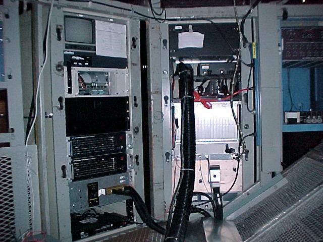
The two electronic racks installed near the instrument at
Cass...NB this is an old photo, and the rack patch panels have been
changed
The airhose and the two heavy black cables must be arranged carefully in the Cass cage, as shown in the two photos below:
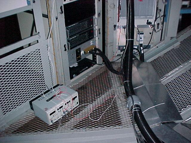

Cable layout in Cass cage: (L) looking West toward racks;
(R) looking North, under PALAO
[NOTE: we no longer use that
little stand-alone PS for the air hose fan].
*** FIGURES: KEY PARTS OF PALAO/PHARO ***
Click on FIGs, or, for hard-copy perusers, all the figures are collected below...
PALAO (PALomar Adaptive Optics) CONSISTS OF:
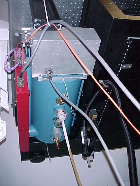
PHARO...the large blue dewar with red electronics box [FIG 1]
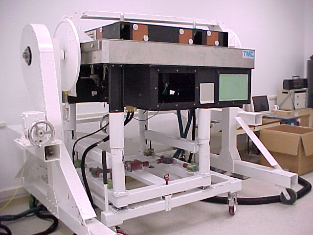
...see Tom Hayward's manual for setup; has a 1/2-ht rack put to left of AO racks in Cass cage.a large, black optical bench housing PHARO and AO optics [FIG 2]
..."stimulus" is on top; main PALAO optics hang under bench; PHARO (absent) would hang at left.2 adjacent electronics racks (tan-colored) [FIG 3]
...the one with a video CRT goes on the left.1 blue-colored rack in mezzanine computer room [FIG 4]
[FIG
1] Blue PHARO dewar mounted on PALAO;
[FIG 2] PALAO optics bench
on its handling cart, parked under the "spit". The PHARO
dewar is absent, but would hang at left.
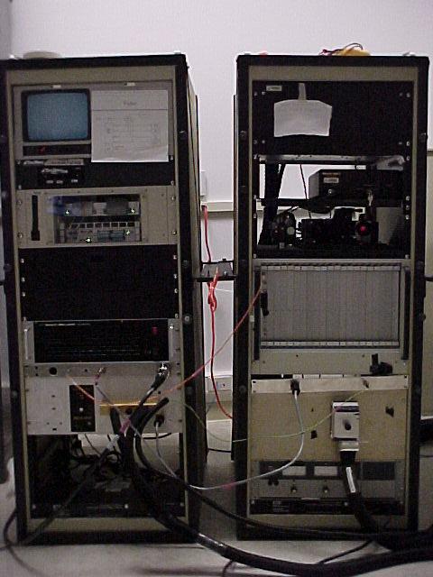

[FIG
3] 2 tan-colored electronics racks, set up adjacent to PALAO;
[FIG
4] blue electronics rack; set up in mezzanine computer room.