
|
|
|
Carnegie Observatories Spectroscopic Multislit and Imaging Camera (COSMIC) Manual
View the original manual.
Contents
- Introduction
- Starting up the COSMIC instrument control window
- An overview of the control GUIs
- Filters
- Focus
- The aperture masks
- The grism wheel
- Flat-field and arc lamps
- Orientation of COSMIC
- The offset guider
- Observing with longslits
- Making multislit masks
- Introduction
- Preparing your object list for the multislit program
- Having the photographic masks made
- Observing with multislit masks on COSMIC
- Direct imaging with COSMIC at the Palomar 60-inch telescope
- Warnings about COSMIC
1. Introduction
COSMIC (Carnegie Observatories Spectroscopic Multislit and Imaging Camera) is a high throughput imaging camera and multiobject spectrograph built by Alan Dressler, Bill Kells, and Anand Sivaramakrishnan (OCIW) for the prime focus of the Palomar 200-inch Hale telescope. It has two user modes: (1) direct imaging and (2) imaging and spectroscopy through reimaging optics. The choice of either mode is made by the PI on the green sheet in advance of the run, and cannot be changed during a night.
The instrument rides in the prime focus cage atop an instrument mounting base with the filter wheel, shutter and guider camera. The camera is controlled by a new ArcVIEW/LabVIEW based GUI that is similar the the other Palomar ArcVIEW camera GUIs. The base, wheels, and guider controls are run within a new LabVIEW based GUI. Image analysis and IRAF based scripts are still run in the IRAF environment.
1.a. Direct Imaging Mode
In this capacity, the CCD is mounted at the focal plane of the prime focus, directly above the filter wheel and the Wynne corrector. Only imaging can be done when the instrument is in this mode. There is only a small amount of vignetting in the corners of the array. The relevant parameters are listed in Table 1.
| Table 1: Direct Imaging Mode | |
|---|---|
| Quantity | Value |
| Focal plane plate scale | 11.86″ mm-1 |
| Pixel scale (measured) | 0.2846″ pixel-1 |
| Field-of-view | 9.7′ × 9.7′ |
| Usable modes | imaging only |
1.b. Reimaged Mode
In this capacity, an aperture mask wheel is located directly at the focal plane of the prime focus, while reimaging optics, a grism wheel, and the CCD are mounted in a pedestal above the focal plane. In this mode, imaging, longslit spectroscopy, and multislit spectroscopy are available. There is some significant vignetting for the imaging which increases rapidly towards the corners of the available field-of-view. There are currently metal and photographic emulsion longslits available of various sizes. Multislit aperture masks are created by the user in advance of the run using a procedure described elsewhere in this manual, resulting in a photographic emulsion which is the mask. The relevant parameters for this mode are listed in Table 2.
| Table 2: Reimaged Mode | |
|---|---|
| Quantity | Value |
| Focal plane plate scale | 11.86″ mm-1 |
| Reimaging factor | 1.4 |
| CCD reimaged plate scale | 16.60″ mm-1 |
| Pixel scale (measured) | 0.3988″ pixel-1 |
| Field-of-view (CCD) | 13.6′ × 13.6′ |
| Usable field-of-view (diameter) | ~ 15.5′ |
| Usable modes | imaging longslit spectroscopy multislit spectroscopy |
| FOV available for multislits | 12′ × 8′ |
1.c. CCD Characteristics
The detector is a 2048 × 2048 pixel SITe (formerly Tektronix) thinned CCD with good UV response.
The characteristics of this CCD are given in Table 3.
Note; The new ArcVIEW based camera GUI enables sub-rastering the array and any imaginable binning combination.
| Table 3: COSMIC CCD Characteristics | |
|---|---|
| Quantity | Value |
| Pixel size | 24 µm |
| Array size | 2048 × 2048 pixels |
| Peak QE ( nm) | ~ 88% |
| Read noise | 12 e− |
| Gain | 3.1 e− / DN |
| Time to readout | 112 seconds (no binning) 29 seconds (4×4 binning) |
| Orientation, imaging (base PA=180°) With spectrograph tower |
N down, E left (display ccd001 1)N up, E left ( display ccd001[*,-*] 1)
|
| Orientation, spectroscopy (base PA=180°) With spectrograph tower |
E left, blue down (display ccd001 1)E left, blue up ( display ccd001[*,-*] 1) |
| Orientation, imaging (base PA=180°) Direct imaging |
N up, E right (display ccd001 1) |
| Overscan | pixels x = 2038:2048 |
| Dark current | unknown |
| Bias | bias ~480 DN |
| Minimum texp (photometry) | 2 seconds |
2. Starting Up the COSMIC Instrument Control Window
2.a. Starting COSMIC
The instrument support engineer should setup the instrument into its normal configuration, and do simple tests to insure that the setup is complete. The camera GUI windows will be open on the workstation monitors in the 200-inch control room. In other words, with the new LabVIEW system, COSMIC will be up and running when the observer arrives. In case of crashes the GUIs are restarted with icons that live on the workstation monitors. The instrument support engineer will give you a quick run down on how to start the system in case of trouble.
2.b. Inserting the Appropriate Filter, Aperture, and Grism Names
Generally, the filter and grism wheels have default elements and are unchanged run to run. If the observer wants to change an element in these wheels it is done through the Green Sheet sign up or by contacting instrument support directly.
The aperture wheel is usually populated by the visiting observer. Some instruction on this process is in this manual and more info is available on the mountain. Of course it is best to have instrument support, or the daycrew, show you how to insert the apertures. The names on the wheel GUI menus are changed by hitting the stop button at the top of the wheels GUI vi. Next right click on the pull down menu for that wheel and select properties. In the pop-up window that appears, select edit items to change the aperture wheel names.
3. An Overview of the Control GUIs
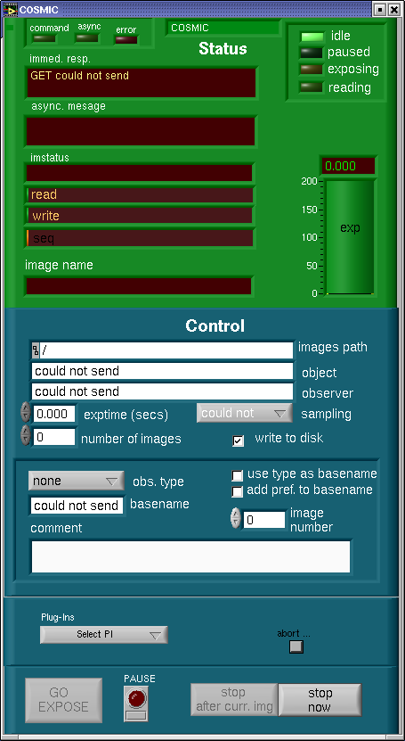
Main GUI window. |
3.a. The Main Camera GUI
The following is a introduction in how to run the Arcview camera GUI.
For a more detailed training session, contact Jeff or Kevin on the mountain to
set up a hands on run through.
The camera GUI is the Palomar ArcVIEW standard camera GUI that is in use on DBSP, TSPEC, Echelle, Wirc, CCD15, and FLI. The top of the GUI in light green is camera status. The lower part of the GUI in dark green is camera control. The status part is pretty much self evident. In this version of the user's manual we will concentrate on the camera control and leave the status side to a later update.
At the top of the control section is the images path. This path is set at startup
to /rdata/COSMIC/"the UT date" (eg.20090118).
Do not try to change this path.
To get to your data from the workstation computer, ssh as user to the computer that
is running the camera. Ask instrument support for passwords etc.
The next two boxes are object and observer information that goes into the fits image headers.
The exposure time can be entered by keyboard after mouse clicking in the exptime box.
The same is true of the number of (successive) images box. The arrow keys next to each
box can also be used to increment the values by one. The sampling box is a leftover
from the TSPEC GUI and when I get the time I will delete it. The final item in this area
is the write to disk selection. It is probably a good idea to leave this selected
because at the moment we do not have realtime display of the image.
The next section down has a pulldown menu obs. type which selects the type which goes
into the fits header. The only selection which actually does anything is dark which
leaves the shutter closed. Below that is the basename box which selects the fits file
prefix (eg.enter cos first file name is cos0001.fits). use type as
basename is buggy,
don't use it. Soon it will go away.
The image number is the next image number that will be used. It increments automatically.
It can be clicked on to edit. The GUI will never delete data if the image file name is duplicated.
The GUI adds a -0 to any files that have identical numbers.
The next box is for comments. Important note: never use commas nor semi-colons. The GUI interprets these as "wait for next command," it will hang the GUI.
The next section has a pull down menu for module Plug-Ins. The pulldown menu is a standard menu used in other GUIs. For COSMIC only one plug-in is useful. Use this menu to get the ROI (region of interest) GUI. This GUI is described below. The small button to the right of the pulldown is called abort... Click this button and two hidden buttons appear, QUIT and ABORT. QUIT cleanly shut down the GUI. Use this button if the GUI hangs. My advise is to never use the abort button to stop an exposure. It can hang the system. Use the stop button below to cleanly stop an exposure.
At the bottom of the GUI are the expose and stop buttons. Obviously GO EXPOSE starts an exposure. The PAUSE button closes the shutter and lets the observer change the exposure time. Click PAUSE a second time and the exposure resumes. stop after curr. img. stops a sequence of exposures after the current exposure is done. stop now cleanly stops and reads out an image. This is a much better choice for aborting an exposure.
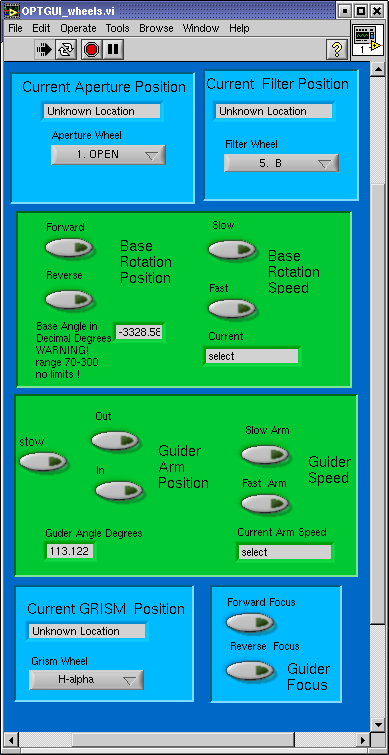
Wheels GUI. 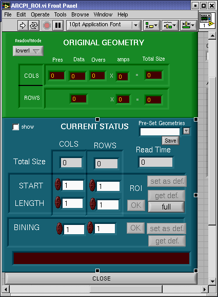
Region of interest GUI. 
Guider head calculator. |
Important note: starting the COSMIC icon on the workstation computer starts
a vnc session on the computer that controls the camera. It is supposed to start a "sharing"
program that enable serial communications for several GUIs. If starting the wheels or
calculator GUIs fails, quit the camera GUI and restart using the icon in the cosmic folder
on the vnc camera computer environment. Contact instrument support and make sure they
show you how do do this.
3.b. The Wheels GUI
After the COSMIC icon on the workstation computer brings up the VNC window and
the camera GUI on the camera computer, find a folder on the VNC desktop labeled COSMIC.
Open this folder click on the wheels_gui icon. This brings up the cosmic wheel control GUI.
This GUI is fairly simple, pulldown menus select wheel locations and buttons control
speeds and encoder devices that move in an "analog" fashion.
Starting at the top of the GUI, in light blue are the aperture and filter wheel controls.
The aperture wheel is controlled with a pulldown menu. Simply pulldown the menu and select
the position desired. The aperture wheel menu may be edited to enter your names for the
aperture masked used in observing. Ask Instrument Support how to do this. If COSMIC is
in direct mode the aperture wheel will not be connected and the window will indicate
Unknown Location. The filter wheel operates just like the aperture wheel using a
pulldown menu.
Important note: do not use the grism or aperture wheels in direct mode, you will hang the GUI.
The next frame is the base rotation window. First select Base Rotation Speed (fast or slow). Next to rotate the COSMIC base simply hold down the Forward or Reverse button. The angle will update in the base angle window.
The next frame down is the guider control window. First like the base rotation one selects the Guider (arm) Speed (fast or slow). Then click and hold the Out button to move the guider arm out of the stow position. Keep holding the Out button down until a suitable guide star shows in the guider camera window. Once a star is found, focus the star with the guider focus control buttons in the light blue frame just below the guider arm control frame. When guiding is done and you want to slew to a new location, press the stow button to send the guider arm back to the safe (overexposure safe) location.
The final frame at the bottom of the GUI is the grism wheel control. This is just like the aperture and filter wheel controls. Use the pulldown menu to select desired location.
Important note: the GUI comes up with pulldown location that are default programming locations that probably have nothing to do with the actual wheel location. At start up in reimaging mode, send the aperture, filter, and grim wheels to some location to sync up the menu and location indicators. In direct mode only do this to the filter wheel.
3.c. The Region of Interest GUI
As mentioned above the ROI GUI is brought up in the main camera GUI with the pulldown plug-in menu. As with the camera GUI the top half is status (or setup) and the lower half is control. This GUI is used to subraster or bin cosmic images. Note that the subrastering is set by starting pixel and length of sub-region. To make changes type in numbers in a window, hit return, press OK, and press set as def. to save your changes. The binning selections are done the same way. Notice that the Read Time value changes with subraster or binning changes.
As always, if these instructions are too vague or unclear, contact Instrument Support for... support.
3.d. The Guider Head Calculator
The GHEAD GUI is brought up with the GHEAD icon in the COSMIC folder just like the wheels GUI. Click the icon.
The GHEAD calculator is needed to tell the telescope where the guider arm
and base angle are. These values are combined to orient the guider move.
The values are updated by pressing the right arrow button at the top of the GUI.
At that point tell the telescope operator the ghead value. At this point the
operator needs to enter that value manually. Soon I will automate this. Promise.
The telescope operator will operate the Shepard Autoguider once you've selected a star with the guider controls and given the GHEAD value to the operator. If you've used COSMIC or DBSP before and feel confident, the telescope operator can show you how to use the Shepard Autoguider.
4. Filters
The filters are located in the "pizza box" just below the focal plane, which is in the converging beam at prime focus.
4.a. Standard Filters
The standard filters provided with COSMIC are given in Table 4. The first position is normally left clear (i.e. an empty filter holder ring) to allow for spectroscopy in the reimaged mode.
| Table 4: Standard Filters for COSMIC | ||
|---|---|---|
| Position | Filter | Focus offset (Foc[filt] - Foc[r]) |
| 1 | clear | ~ -1.2 mm |
| 2 | g | - 0.2 mm |
| 3 | r | + 0.0 mm |
| 4 | i | + 0.1 mm |
| 5 | B | - 0.3 mm |
| 6 | V | - 0.1 mm |
| 7 | R | + 0.0 mm |
4.b. Installing Your Own Filters
Not anymore. The current practice is for the Palomar staff to install visiting astronomer's filters. Please note on your green sheet well in advance of your run, any filter changes you would like to make and we will take care of them for you.
There are now many empty filter rings available, so that users who bring their own filters do not have to remove the standard filters from their rings. The standard filters have their name (BVRgri) engraved on the side of the filter ring.
The filter rings are 4 inches in diameter. There are also a set of five adapters to mount 2-inch square filters into the filter rings. Larger filter adapters need to be custom made.
Inserting and removing the filters from the instrument is a difficult process, so it is required that a member of the day crew make any and all filter changes.
NOTE: the following filter insertion instructions are left in this document for the benefit of the Palomar staff.
It is necessary to use a clear plastic device to insert/remove the filters; this tool is kept in the black carrying cases. In the prime focus cage, you should move one-quarter way around the cage in the clockwise direction. At waist level is the entrance to the "pizza box", which has a clasp to open/close it. It is usually easiest to squat or sit on the floor of the cage in order to insert/remove filters, but note that there is a thin metal lever arm that holds each filter in place that is at eye level when you sit on the floor of the cage. For this reason, you should always wear protective glasses when inserting/removing filters.
In order to move the filter wheel, you need to press the appropriate buttons on the blue motor controller box in the prime focus cage. The filter wheel can be incremented by pressing the FILTER button followed by the INC button. There is an alternative DEC button to decrement the filter wheel. In order to install a filter, you need to press FILTER followed by INSTALL; this moves the filter wheel by a half-position, allowing access to a given filter. Since the installation position is on the opposite side of the filter wheel from the focal plane, the filter being installed is filter position plus four modulo seven.
Each filter position MUST have a filter ring in place in order to turn the filter wheel. There are many spare rings, so if you want a clear aperture, just insert a spare ring.
You should attempt to have the filter wheel roughly balanced - in other words, do not put filters in slots 1-4 and empty rings in slots 5-7, but alternate filters and empty rings.
Always press FILTER on the blue motor controller box when finished installing or removing a filter, in order to move the filter wheel from a half-position (installation) to an integer position (observing). Not doing this will prevent the wheels GUI from successfully moving the filter wheel. NEVER move the filter wheel by hand!
5. Focus
5.a. Focusing the CCD
In /home/user/bin on the workstation computer you will find a focus script
called cosfocus.
This is a basic focus script, other scripts modified by recent observers mimic the LFC focus script.
Take a look at these scripts, make new onesas you desire. Please do not delete any pre exisiting scripts.
It is suggested to use 0.2 mm steps to get a rough focus, 0.1 mm steps in good seeing, and 0.05 mm steps only in the very best seeing.
The spacing between the first and second exposures is twice as big as between the remainder of your focus exposures.
Approximate focus for COSMIC in the reimaged mode is 22.0 mm for the r filter. Approximate focus for COSMIC in the direct mode is 21.0 mm for the r filter. Other filters (and filterless) foci relevant to the r filter are given here for the standard filters.
5.b. Focusing the Guider
When you have found a guide star and have successfully focused the telescope, you will want to focus the guider. There is a Guider Focus box within the COSMIC Wheels GUI. Use the focus in and out buttons to get the focus you desire. See the Control GUIs Overview section to learn how to aquire and focus the guider camera.
5.c. Focusing the Spectrograph
The reimaging optics tower has a temperature-sensitive focus that has been mostly eliminated by a temperature-controller device now wrapping around the reimaging optics. Thus there should be no need for the observers to focus the spectrograph onto the aperture masks. If the focus appears to be poor you should contact an appropriate Palomar staff person, or one of the instrument builders, for advice. It is very easy for an inexperienced person to destroy the optical alignment of the instrument, so the procedure is not described here.
6. The Aperture Masks
Please also look at an excellent COSMIC notes by Jason Surace.
6.a. Description
In the reimaging/spectrograph mode, the observer can choose between a series of available longslits or can prepare his/her own multislit mask. There are six aperture positions; one is permanently clear, while the other five are available for various masks. There is no standard mask set-up. As it has aged, COSMIC has become mainly a multi-object spectrograph. The aperture wheel has no standard set-up. It is the observer's resposibility to bring the aperture masks needed to complete his/her science goals. See the section on aperture masks in this manual.
There exist two kinds of slitmask holders: the "older", flat-topped version, onto which the masks are attached using tape; and the "newer" version with a metal cover that locks on top of the mask itself. There are 5+ of each kind available in one of the COSMIC black pouches, although one or more of each kind appear not to work (and are labelled as BAD).
It is recommended that you do not use the metal longslit, as it has collected a great deal of garbage onto the slit opening which results in an uneven width along the slit. It is suggested that you use one of the film longslits instead.
6.b. Mounting a Photographic Slitmask Onto a Holder
To mount a photographic film slitmask onto a holder you will need: a light table; scissors; narrow black tape (for blocking out the mask border); and a jeweler's screwdriver. All except for the black tape can be provided by the day crew. The tape should be bought in town; good examples are "Letraline 476 3/16-inch black matt 3730" or "Letraline 96 1/4-inch black flex 2426." Call around for a graphic design store to find such tape. You may also use the black photographic tape which is kept in the wooden desk just outside the control room, on the observing floor.
Using scissors, trim the slitmask film to keep ~1/4 inch outside the rectangular mask border. Also, diagonally cut off the four corners of the film.
Take a mask holder and remove the cover (there should be four screws holding it in position). There are three notches cut into the outer ring of the holder. One notch is closest to a short side of the rectangular mask hole; place this notch facing towards your left. Turn your slitmask upside down so that the label reads backwards and lies in the upper right corner, and place on top of the mask holder. Place the cover on top, and lightly fix in place with the screws, leaving it loose enough so that you can still move the film around.
Place the mask holder on the light table. Slide the film around until the upper/lower mask border lines up with the upper/lower edge of the rectangular cutout of the mask holder. This is a crucial step to do carefully, as it sets the rotation angle of the slits in the mask. When you are satisfied, tighten the four screws to fasten the film in place.
Use the black tape to cover the four clear borders of the film and the label. Also cover any imperfections in the black portion of the emulsion.
6.c. Installation
Inserting and removing the masks from the instrument is a difficult process, so it is required that you be instructed by a member of the day crew or an experienced observer.
As you enter the prime focus cage of the 200-inch telescope, move around counter-clockwise to provide easy access to the blue box (the COSMIC local motor control console). Assuming the zipper on the COSMIC dark shroud is in its usual place, you also then will have easy access to a velcro-closed opening in the shroud at about waist level. Open this to get access to the aperture wheel. The first time you try this you might want to unzip the zipper on the COSMIC dark shroud, so that you can see the entire instrument more easily. (Sometimes the setup crew leaves this shroud in a position rotated from its correction orientation, so you might have to remove the shroud anyway.)
Use the blue box to move the desired aperture wheel position to the install location. First push AP to select the aperture motor, then push INC or DEC to move the wheel. The position displayed by the blue box is the position of the aperture wheel that is in the optical path; the position in the installation location at that time is 2 positions less (modulo 6).
Reach over the blue motor housing mounted just above the aperture wheel on COSMIC. Hold the holder so the "locating notch" is pointing away from the blue motor housing. Insert the holder and mask so that the 3 notches all clear, then press down, and turn clockwise approximately 1/4 inch, after which you will hit a stop. The stop is defined by knife blades hitting the beveled edge of the each of holder notches. For peace of mind, tape the holder to the aperture wheel once the holder is installed.
Repeat this procedure using the blue box to move to each desired position on the aperture wheel for each mask you plan to use.
Be sure to close the velcro flap on the shroud prior to leaving the prime focus cage.
Once you are back in the control room, cycle through several different positions on the aperture wheel to reset it properly.
7. The Grism Wheel
There are two available grisms in the reimaged/spectrograph mode: 300 l/mm and 600 l/mm. There is no available tilt for the grisms, so the wavelength coverage for the standard longslits is fixed. See Table 6 for a description of the grisms.
It is possible to obtain a different center wavelength by constructing a longslit (or multislit) mask that is offset in the focal plane along the dispersion direction. See the section on making multislit masks for a description of how to do this.
Interference filters are best placed in a parallel beam, so that their appropriate place in this instrument is in the grism wheel. Judy Cohen has a filter holder for the grism wheel; see her to use it. The clearance at the top of the filter holder is small, so it requires shaving off the top of the screws.
| Table 6: Grism Wheel | ||||
|---|---|---|---|---|
| Position | Grism (l/mm) | Blaze (Å) | Center wavelength (Å) | Mean dispersion (Å pixel-1) |
| 1 | 300 [a] | 5500 | 6500 | ~3.1 |
| 2 | clear, available | |||
| 3 | 600 | 4800 | 5000 | ~1.46 |
| 4 | as of 2004 in use with Hα filter | |||
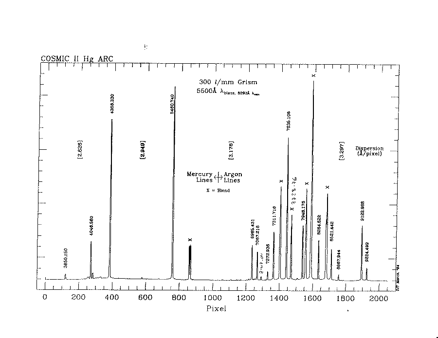
| [a]
Arc spectrum for 300 l/mm grism,
courtesy of Dave Thompson; hand-written lines may be line-blends, so be wary!; also table of the lines in format suitable for use in IRAF twodspec reductions. | ||||
8. Flat-field and Arc Lamps
The lamps are turned on or off using the TCS terminal, ask the daycrew or support
astronomer to help you the first time.
All lamps are turned off using the command LAMPSOFF.
All of the lamps are mounted above the prime focus cage, pointing up. All flat-fields and arc lamps require the telescope to be pointing at the dome; imaging dome flats should be taken with the telescope vertical and the shutters closed (to point at the white painted portion of the dome). The primary mirror cover must also be in the open position (see someone on the daycrew to show you how to do this).
The appropriate lamp for direct imaging flat-fields
is turned on with the command LOWLAMP.
The appropriate lamp for spectroscopic flats
is turned on with the command HIGHLAMP.
The arc lamp (Hg and Ar together) is turned on with the command ARCLAMP.
The typical exposure times for some of the flats and arc are given in Table 7.
| Table 7: Typical Exposure Times for Flats and Arcs | ||
|---|---|---|
| Setup | Lamp type | Exposure time (s) |
| Imaging, g filter | lowlamp | 30 |
| Imaging, r filter | lowlamp | 8 |
| Imaging, i filter | lowlamp | 3 |
| Spectroscopic flat, 1.5″ slit | highlamp | 4 |
| Arc (Hg+Ar), 1.5″ slit | arclamp | 180 |
9. Orientation of COSMIC
9.a. Direct Imaging Mode
 N
W E
 S
The rotation of COSMIC is controlled in the instrument window by the
Base Position Angle. The nominal angle is 180°, which produces the
following orientation for the IRAF command display ccd001 1:
9.b. Reimaged Mode
 S
E W
 N
The rotation of COSMIC is controlled in the instrument window by the
Base Position Angle. The nominal angle is 180°, which produces the
following orientation for the IRAF command display ccd001 1:
For this display mode, spectra will have blue at the bottom of the
image.
 N
E W
 S
For the IRAF command display ccd001[*,-*] 1, the orientation is:
which is the usual sky parity.
For this display mode, spectra will have blue at the top of the
image.
 W
N S
 E
If the Base PA is set to 270°, then
for the IRAF command display ccd001[*,-*] 1, the orientation is:
 E
S N
 W
If the Base PA is set to 90°, then
for the IRAF command display ccd001[*,-*] 1, the orientation is:
In the default Base PA of 180°, the longslits will run E-W (i.e. slit PA is +90°).
If you wish for the slit PA to be +45°, for example, then you will set the Base PA to be 225°.
The Base PA has an allowed range of between 70° to 300°.
10. The Offset Guider
The COSMIC wheels GUI controls an offset guider arm to vary the position of the offset guider camera and its focus. There is usually no difficulty finding a sufficiently bright star within the full travel of this guider arm.
10.a. Finding a Guide Star
This is also covered in the Control GUI section.
The guider control window is in the wheels GUI. First like the base rotation one selects the Guider (arm) Speed (fast or slow). Then click and hold the Out button to move the guider arm out of the stow position. Keep holding the out button down until a suitable guide star shows in the guider camera window. Once a star is found, focus the star with the guider focus control buttons in the light blue frame just below the guider arm control frame. When guiding is done and you want to slew to a new location, press the stow button to send the guider arm back to the safe (overexposure safe) location.
10.b. Guiding on a Star
Once you have found a star to guide on, you will need to use the Shepherd Autoguider (large monitor). The telescope operator can show you how to use this guider, or he/she can set it up for you. Alternatively, follow the above link to the autoguider web page for more information.
10.c. Important Warning About the COSMIC Guider
Because the COSMIC guider has an automatic gain setting, it is extremely important to "STOW" the guider before slewing the telescope, and also before turning on the lights in the dome. Failure to do so may very well permanently damage the camera.
11. Observing with Longslits
There are two kinds of longslits which you might consider: (1) the metal slit (1.5″), which is quite dirty and hence of uneven width; and (2) the photographic film slits. For the latter, several are left with the COSMIC black carrying pouches; you should see the section on mounting/installing slitmasks.
This section assumes that the slits are already installed in COSMIC.
11.a. Determining the Position of the Slit
In the afternoon, you should take pictures of the longslit(s) you will use, in order to measure the CCD (x,y) target position you want to place a given galaxy/star. This images should be taken with the FILTER=CLEAR, GRISM=CLEAR, and APERTURE=longslit of your choice.
You should take images in both unbinned mode (1 × 1) and the quick binned mode (set binning to 4 × 4 in the ROI GUI). The latter has a quicker readout (30 versus 150 seconds), so for all but the faintest objects it is the setup imaging method of choice.
Display the images and choose a good part of the slit near the
center to place the object. Use the IRAF task IMEXAMINE with
option a to get a reasonable estimate of the (x,y) pixel value
for the slit. Create a file with one line and the x and y pixel
values entered on that line (separated by whitespace). Create
different files for the unbinned mode and the binned mode.
11.b. Placing an Object Onto the Slit
An IRAF script called TELOFFSET has been written to assist in placing
an object onto the slit using the file created in the previous
subsection.
Focus the telescope with FILTER=CLEAR, since you will not be using a filter for the spectroscopy.
Go to your field and set the COSMIC base position angle to your desired angle (where COSMIC BASE POSITION ANGLE = 270 − TRUE PA; and COSMIC BASE POSITION ANGLE must be between 70 and 300).
- Take an image (either unbinned or binned) with FILTER=CLEAR, APERTURE=CLEAR, and GRISM=OPEN.
- Display the image by flipping the y-axis, i.e.
display ccd123[*,-*] 1. - Edit the parameters for TELOFFSET, i.e.
epar teloffset. Enter the appropriate filename created in the previous subsection, the current COSMIC BASE POSITION ANGLE, and identify if this is a unbinned image (SNAP=no) or a binned (4 × 4) image (SNAP=yes). Type:goin order to run the task. Find the object in the SAOIMAGE display, typeato identify it, and thenqto quit. The appropriate telescope offsets needed to move this object onto the chosen slit position will be shown. - Tell the telescope operator the offsets to execute.
- Find a guide star and start guiding.
- Take another image and repeat steps 1 – 3. If your object is very faint, or if it is a crowded field, you might have to use the unbinned mode. If the offsets are < 0.3″, then this is sufficient. If not, put the guider in "follow" mode, ask the telescope operator to execute the offsets, then enable guiding.
- You should be done. If you are unsure, then repeat step 6 until you are fully satisfied.
12. Making Multislit Masks
12.a. Introduction
An important element of most modern spectrographs is their ability to take spectra of many objects simultaneously using either multiple slits or optical fibers. While this is an extremely efficient method of utilizing telescope time, it comes with a price of the much higher level of preparation in advance of your run, and time for setup at the telescope (both during the day and while observing).
In order to prepare for observing multiple objects, you need to have an object list with high-quality relative astrometry (better than 0.3″ is usually required). Most observers do not bother to observe astrometric fields, and hence their data are often not of a sufficient quality to do the kind of astrometry required for multiobject spectroscopy.
In order to illustrate this point, imagine that you wish to observe faint galaxies along a strip with COSMIC in order to obtain redshifts. You choose to use a 1.5″ slitwidth, which is typical for this application. You want to keep the objects on their slits to within 0.25″ rms, because a 3 deviation would then put a given object halfway off the slit. This means that you need to know the plate scale and distortions in your preparatory CCD imaging to an accuracy of 0.25 / 240 = 0.1%, to cover the full 4′ = 240″ perpendicular to the slits. So if the pixel scale on your CCD is ″, then you would need to measure that scale to an accuracy of 0.0003″. If there were additional distortions in your field-of-view (extremely likely!), then you would have to characterize these fully across the full field to this same accuracy. Needless to say, many observers do not bother themselves with measuring these effects to the required accuracy.
An excellent way to characterize the plate scale and distortions in your input images is to observe one or more star field which has many stars with high-quality coordinates (like well-studied globular clusters).
12.b. Preparing Your Object List for the Multislit Program
The available field of view for COSMIC multi-slits is ~13′ × 8′. It is suggested that the width of the multi-slit pattern be less than 4′, preferably even less than this, to ensure that the spectra have approximately the same central wavelength (and hence spectral coverage) and to avoid problems with spatial distortion. Since the multi-slit masks are made by a photographic reproduction process, the width of each slit can be set by the user.
A FORTRAN program exists for converting an object list into a 4 times
enlargement negative version of the slitmask. It is called
cosmicslitmask.f and can be found
following this link (see also its
README file).
The COSMIC slitmask assignment program takes a list of offsets
(arc-sec East and arc-sec North, where East and North are
positive) of objects from the center of a field. It is a simple program,
assuming a constant plate scale (11.9″/mm) for the prime focus, and
ignoring the complications of spatial distortion, gnomic projections, etc.
The output of this program consists of a text file and a plot file. You should create two separate plot files—one which includes the object number above each slit, the other with only the slits and the identification label. The latter plot is the one that needs to go to the photographic lab for reduction.
Note the field identification label on the upper left corner of the plot. The position angle for the mask in terms of the COSMIC "base position angle" is given in this label. The limits on rotation for the COSMIC base position angle is 70° to 300°.
Make sure to take to the mountain printed copies of all 3 of these files (one text and two plots) for each mask you design. You should also have a good image of the field with all of the objects identified.
c. Having the Photographic Masks Made
The slit masks used by the COSMIC spectrograph are made by reproducing photographically at a reduction factor of 4 the output of the COSMIC slit mask assignment program. Thus the slits correspond to places where the film is clear (but there is still some transmission loss of course), and the remaining area must be very opaque. If the contrast in transmission between the slit and the dark area is not at least 104, then sky light may well leak in and contaminate the exposure at a noticable level. Thus the two critical concerns for the photographic lab are the exact reduction by a factor of 4 of the supplied image and making the mask area (except for the slits) as opaque as possible.
The printed mask should be taken to:
Commercial Graphics
681 South Raymond Ave
Pasadena, CA 91105
(626) 583-1122
Note that the actual negatives are shot in their LA office, but materials may be dropped off and picked up in Pasadena. Tell them you would like a 4X reduction of each mask, on extremely opaque negatives, with reverse reading. Make sure to tell them you will actually want the negative itself. Four masks can be placed on a single sheet of negative, for a cost of about ten dollars per sheet. It is good practice to have two copies of each mask made, as small defects are not uncommon.
13. Observing with Multislit Masks on COSMIC
13.a. Preparatory Work in the Afternoon
You should write a tape at your home institution including the
tabular output files from cosmicslitmask.f. Dump these
files into your current COSMIC directory on the COSMIC Sparc
computer (i.e. where the data are being written).
For each mask you need to create a file containing your alignment objects.
This should be done in the afternoon before observing, and the file should be in the
same directory that you are using for taking images. This can be done
easily by editing the tabular output of the cosmicslitmask.f program:
(1) remove the header line(s); (2) keep only 5-10 objects that
are good for slitmask alignment; and (3) reorder them so that the
objects go from left to right (in the plot of the slitmask).
A good object for slitmask alignment is relatively bright and
compact, so that an accurate centroid can be measured in a relatively
short imaging exposure. Call this file mask.slits.
You will need to mount your masks into holders and then insert them into COSMIC.
Take a direct image of each of the slit-masks you have just installed. This images should be taken with the FILTER=CLEAR, GRISM=CLEAR, and APERTURE=multislit of your choice. You can take these with the mirror closed, using only the ambient light in the dome (before 4 pm), with an exposure time of 10s.
Display the image of the desired slit-mask (with the [*,-*] orientation).
Once you have taken the images, use the IRAF script masksetup
to mark the positions of the slits corresponding to the objects
in the mask.slits file. In IRAF, type masksetup. You will be asked
for an output filename (typically mask) and the input filename (typically
mask.slits). You will then be asked to press the b key
at the left and right edges of the slit corresponding to your first object,
followed by q, then
the a key at the center of slit, followed by q. This will be repeated
for each alignment slit. After the last slit, the calculated positions of the
objects will be marked on the screen, and an output
file called mask.ap will be produced which will be used during the night
for alignment.
Other Comments
If you wish to sample a wavelength range that is not centered on the standard
wavelength of the grism, this can be
accomplished by moving all of the slits up or down (in the y-direction) in the
slitmask field-of-view. This is typically not a
reasonable course of action for the 300 l/mm grism, since its
spectral coverage includes nearly the entire optical spectrum.
But it may be of interest for users of the 600 l/mm grating
(central wavelength is 5000 Å). For the latter grism, the spectral
scale of 1.6 Å per pixel, the field-of-view in the y-direction of
, and the scale of 0.4″ per pixel, result in
an available range of Å for the central wavelength.
(With this grism, the full spectral coverage is approximately 3200 Å.)
You will need to avoid the label in the upper-left portion of the mask,
and should be advised that any distortions in the COSMIC field-of-view will be
more pronounced as the slits are placed further from the center of the
field. Moving the slits upwards (in the positive
y-direction) will shift the center wavelength towards the red. This
can be done in the cosmicslitmask program (option 10)
which you use to create the slitmasks.
The scale of your input object coordinates should be known quite accurately; using a "word-of-mouth" CCD pixel scale, or one listed in a handbook, might not be as accurate as you might think. The best solution is to observe a globular cluster with the same CCD setup as you observed your multislit object field, and then use astrometry programs to get a good plate scale. Better yet, you can use many stars (> 100) from the cluster to get a mapping of the CCD distortion, and correct your object coordinate list for this effect. For illustration purposes, a 0.5% error in the plate scale will cause a shift in the slits by 1.2″ for a 4′ wide set of multislits, which is comparable to the typical slit width of 1.5″. Accuracy of 0.2% or better in the plate scale is a reasonable goal.
The focusing of the CCD camera on the apertures is dependent on temperature. This adjustment is not typically done by the setup crew, but should be considered by the observer. Measure the slit widths (FWHM) in the afternoon and determine if they appear to be in an acceptable focus. The focus procedure requires two people, one in the cage turning screws and the other at the computer taking images and measuring FWHMs. Contact experienced individuals before attempting this procedure, as mistakes can be destructive to the alignment of the instrument. It is also important to note that the optimal focus for the longslit and for your multislits might be different, so you may have to choose which one to optimize.
13.b. Procedure for Aligning the Multislit Mask
The IRAF script MASKALIGN is used to align your masks. Set the COSMIC base
position angle to the correct value, which is
indicated in the slitmask plot label. First, take a
short (30s) exposure of the field you will be using your mask on. Do not use
any filter
(filter position 1, clear), and leave the aperture (aperture position 1, clear)
and grism (either position 2 or 4) wheels open.
When the image has read out,
display it (with the [*,-*] orientation). Execute MASKALIGN, which will
prompt you for the input file with slit positions (mask.ap, but without
the .ap), and the image to work on.
This program will then draw circles around the positions corresponding
to the desired positions (in the slitmask)
of the objects you have identified. This may be many arcseconds away from
their actual positions in the image! Move to the objects in the order they
were entered into the file,
and at each one, put the cursor on the object, then hit the spacebar.
After the last object, type q (for "quit"). (You will need to
"quit" twice, first in the display window, then in the IRAF window.)
This produces an output in the IRAF window of the mean offset for X and Y in arcsec and for Theta in degrees, as well as errors from the mean fit in X and Y for each object. For a properly made and mounted mask, the errors of the objects with respect to the fit will be small, under 1.5″ even when you are quite far off in pointing and/or rotation angle. If you see larger errors, either the coordinate list fed into the mask design program is incorrect or there has been a mistake in how the mask was mounted. If you see large errors of alternating sign, the most likely flaw is that the mask has been loaded upside down, and needs to be flipped with respect to the holder.
You will then be prompted to type in the COSMIC base position angle, so the offets in X and Y can be rotated into offsets in RA and Dec. Move the telescope as required. If the offset dRA is positive, move East. If dDEC is positive, move the telescope North. Add dTHETA to the COSMIC base position angle and rotate COSMIC as required. If the required rotation angle is less than 0.1, then you should not adjust it.
Two iterations will probably suffice for most fields given reasonable centerfield coordinates and telescope pointing. You should obtain a guide star after the first iteration (i.e. after the first telescope offset, and before starting the second image exposure), as this is an integral part of the final alignment. If it is necessary to make small moves after the first iteration, the guider can be placed in "follow" mode, the telescope moved, and guiding restarted.
You should now insert the appropriate mask and grism, and start taking your spectra. The entire alignment procedure should take about 12 minutes (6 of which are readout).
14. Direct Imaging with COSMIC at the Palomar 60-inch Telescope
NOTE: The 60-inch telescope is now a dedicated automated system. COSMIC is no longer used at the 60-inch. The section below is obsolete but is still included just in case the 60" mission suddenly changes.
It is possible to observe with COSMIC at the Cassegrain focus of the Palomar 60-inch telescope. In this setup, only the COSMIC CCD dewar, readout electronics, and computer (Sparc + PC) are used.
The filters are contained in the standard P60 CCD filter mounting base. There is a complete set of 3-inch filters for this use: UBVRIgriz. The filter motor is controlled by the VAX (username: CCD), not by the COSMIC computer. The standard filter motor commands are: FZERO (to zero the filter wheel, and change the filter names); FMOVE (to move to a new filter); and FSTAT (to display the current filter complement and setting).
The standard P60 offset guider is part of this setup.
The orientation of the COSMIC CCD in this configuration is non-standard, such that North points from the vertical. Rotation is possible using the Cassegrain mounting ring, but is difficult and many observers will choose to ignore this.
The COSMIC CCD and Palomar Observatory's CCD 13 are both high-QE, thinned, pixel2 arrays that were produced in the same run, hence there is little difference between the sensitivities of the two arrays. The current electronics with COSMIC, however, have nearly twice the read-noise of CCD 13, hence for low-background applications (like U-band or narrow-band imaging) CCD 13 is the array of choice.
15. Warnings About COSMIC
The following are items about which all COSMIC observers should be fully aware.
Stowing the guider: It is good practice to stow the guider with the stow button on the GUI at the end of the night, and before any telescope slewing. It is also good practice to click off the frame grabber ENABLE button on the Sheperd autoguider display at the end of the night and before slewing the telescope.
The shutter is slow: The COSMIC shutter is not reliable or repeatable for exposures of less than 2 seconds. When using the focus script it is recommended to expose for at least 5 seconds to eliminate seeing effects.
Turning off lamps during readout: There is significant light leakage even with the shroud in place, so gradients will occur if lamps are left on during readout. This leakage also makes most twilight flats nearly impossible to obtain.
Restarting COSMIC window: Quit the current window. Then type cosmic in any XTERM or
CMDTOOL window. The data taken will be written to this directory.
Aborting Exposures: After aborting an exposure, it is necessary to take a short (2 second) SNAP exposure in order to clean the charge off the array.
Twilight imaging flats: The light leaks in COSMIC are bad enough that it is impossible to take proper flat-field images of the twilight sky. The problem is that the light leaks in during the long readout, causing the response to vary due to the readout, not the desired illumination pattern.
Questions? We've answered many common observing and operations questions in our observer FAQ page.
Please share your feedback on this page or any other Palomar topic at the
COO Feedback portal.
COSMIC Manual / v 2.0
Last updated: 15 June 2015 ACM
|
|
|