
|
|
|
Double Spectrograph (DBSP) Cookbook
View the original cookbook.
For all Palomar instrument related questions please contact the Palomar support team.
This Cookbook gives a step-by-step guide to operation of the DBSP (double spectrograph) at the Palomar 200-inch Telescope. For a description of the instrument and information needed for advance planning of an observing run, go to the Overview. The hardware setup will be done by the day crew. The support astronomer will help with instrument checkout. The telescope operator will help with setting up the guider and slitview camera, for which there is separate documentation (see Palomar Autoguider). Many parts of this cookbook were taken from Marco Bonati's DBSP software user manual.
Despite its intended real-time usefulness, the Cookbook contains nuggets of instrument theory here and there that might require some time to digest—so of course a thorough reading in advance of the observing run is recommended to avoid unpleasant surprises at the telescope.
- Hardware setup
- Main GUI interface
- Auxiliary GUIs
- Binning and region of interest
- Custom image headers
- Detector temperature
- Lamp controller
- Synchronization interface
- Important notes
- Setup tasks
- Taking data
- Science object
- Data transfer/media backup
- Brief primer on guiders
Contents
1. Hardware Setup (afternoon of the first night)
- Get to the 200-inch no later than 2:00 pm on the afternoon of your first night to make contact with the support engineer. The support engineer is usually on shift from noon to 10pm, and can normally be found in the office adjoining the 200-inch control room.
- Check the white board in the control room to see if the DBSP has been filled with liquid nitrogen. The dewars are topped off every 10-12 hours. The night assistant and Palomar day crew are responsible for filling the dewars, and logging fill times on the white board. Dewar status may be seen by reading its temperature from the temperature GUIs described below. The temperatures are typically 130K for the red camera, and 163K for the blue camera.
- Check with the staff that the correct dichroic has been installed (changes require taking instrument off telescope, and are done only in the daytime). Your green sheet information is in a logbook located on or near the DBSP control computer desk.
- Check that the correct gratings are installed by asking the day crew.
- Check that the grating tilts have been set by asking the day crew. The day crew should have set them to the values requested on the green sheet you turned in prior to observing.
- Check that the neutral-density-filter knob is set to 0 (it's at top center of instrument in Cass cage, almost level with base of forks holding the spectrograph, and has settings 0,1,2,3)—else an ND filter will be inserted in front of the arc lamp (but not in the sky light path).
- Check that the "dust covers" are open (thin, black-anodized metal covers near the top of DBSP that can be rotated by hand)—the day crew can show you where these are.
- Decide on a filter from the following table (most observers do not use filters):
- All DBSP turret functions are controlled by the LabVIEW-based Turret GUI. The Main GUI shows the current filter wheel location for each light path.
| Filter Wheels | ||||||
|---|---|---|---|---|---|---|
| Blue filters | Red filters | |||||
| Wheel | Designation | Code | Filter | Designation | Code | Filter |
| 1 [a] | B0 | 0 | Clear | R0 | 0 | Clear |
| B1 | 1 | Clear | R1 | 1 | GG455 [b] | |
| B2 | 2 | GG495 [b] | R2 | 2 | Clear | |
| B3 | 3 | – | R3 | 3 | RG610 [b] | |
| 2 | B4 | 4 | – | R4 | 4 | – |
| B5 | 5 | – | R5 | 5 | – | |
| B6 | 6 | – | R6 | 6 | – | |
| B7 | 7 | – | R7 | 7 | – | |
| [a]normally installed
in spectrograph; [b] antireflection coated;
|
||||||
Decide on a slit from the following table:
| Slit Wheel (128″ slits) | |
|---|---|
| Slit width | Readout index |
| 0.5″ | 0 |
| 1.0″ | 1 |
| 1.5″ | 2 |
| 2.0″ | 3 |
| 4.0″ | 4 |
| 6.0″ | 5 |
| 8.0″ | 6 |
| 10″ | 7 |
The slits are controlled with the Turret GUI (see below). The Main GUI gives the current slit location. See the section on the Main GUI.
2. Main GUI Interface (afternoon of the first night)
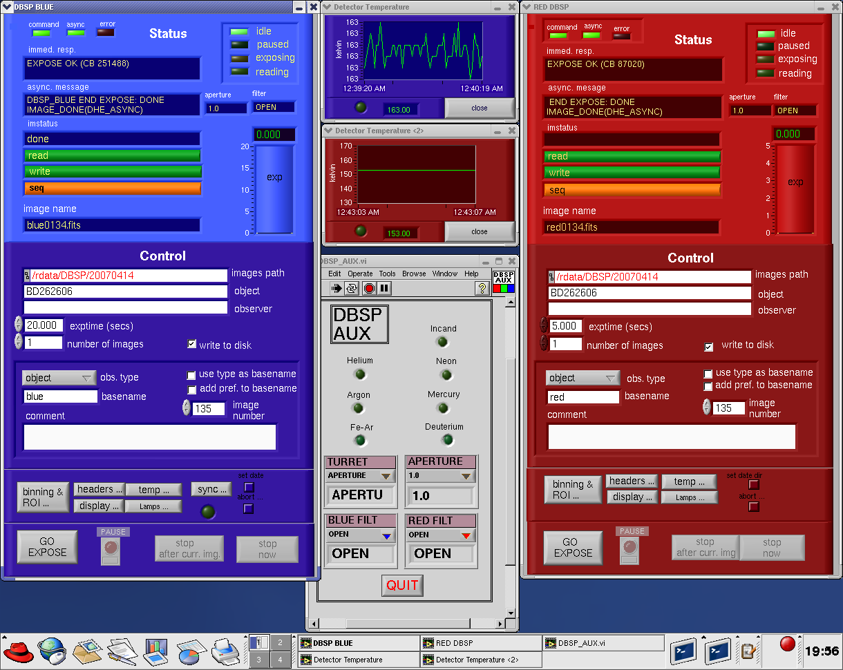
In this picture, one can see the VNC control window that has the DBSP Main and Turret GUIs. The Blue camera Main GUI is on the left. The Red camera Main GUI is on the right. The Turret GUI is in the middle.
When you get to the 200-inch control room, DBSP and its computer
workstation should already be set up. Usually a VNC window will be
open on a control room workstation linked to the DBSP computer on the
Mezzanine level. You should see two Main GUI windows on the VNC:
One
for the red camera, and one for the blue camera. You will operate the
cameras using these two windows. Below is an image of the blue side
Main GUI. The Main GUIs are identical except that the colors are
different (red & blue).
2.a. Main Graphic Interface Window
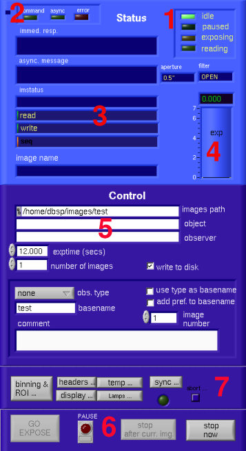
Main GUI window.
The main window allows you to have general control of the camera. It has a status area on the top part, and a control area on the bottom part (the background color is slightly different for the status and control area). The description below applies to both sides except as mentioned above, the sync... button, which is BLUE side only. Note that the sync function does not work at this time.
Status, the upper (light blue) area
- detstatus LEDs: There is one LED per detector status: idle, paused, exposing and reading. This indicates what is the current status of the detector.
- Links and Error LEDs: command, async: These 2 green LEDs indicate if the client is fully connected to the Server. Both LEDs should be green for having full-connection and functionality. error LED: this red LED will turn on when there is any status condition (such as a command that was not received, an erroneous response, etc).
- String status controls and progress bars immediate
response: This status shows the response from the server to ANY
requested action (
EXPOSE, changing image parameter, etc). It will normally be aDONEorERROR <message>. If there was an error, the red error LED (2) will turn on, and the color of the error message will also turn red on the control itself. async: this will show any message that gets to the GUI asynchronously (not necessarily related to a previously sent command). This messages can be just information (likefilter changed, orimage expose done), or reporting a problem (likeTCS connection lost, orCCD temperature too high, etc). aperture: shows the current aperture (in arcsec), read asynchronously from the instrument when it changes. Be patient, this status box takes a few seconds to update. filter: shows the current filter position (filter name), read asynchronously from the instrument when it changes. Be patient, this status box takes a few seconds to update. image name: shows the name of the image that will be (if exposing) , is (if writing), or was (if idle) written to disk. - exp: This yellow, thick bar shows the exposure progress. It can be seen (considering the system is linear) as a "counts" progress. This shows the progress in seconds rather than percentage (elapsed time). The upper limit will expand to reflect the requested exposure time, so it will get full when the requested exposure time is done, whatever that requested time was.
Progress bars: read: this green bar shows the read progress of the current image (in percentage). write: this green bar shows the write progress of the current image (it is normally written to disk as the image gets read). This will not move if the image will not be written. seq: this orange bar shows the progress of the overall sequence. It will get to 100% only when all the images of the sequence are done (which means that the system is idle again).
Control, the bottom (dark blue) area
All the controls can be changed while exposing. Right after the exposure is done, and the readout begins, the current control values are grabbed, so the final image will get those fields (like basename, directory, type, etc).
- Image settings: images path: this is the
directory where the images will be written. object: this is
the object name. This will appear on the
OBJECTfield of the fits headers. observer: name of the observer (it will appear on theOBSERVERfield of the fits headers) exptime: the requested exposure time, in seconds (OEXPTIMEof the image headers: Original Exposure time). number of images: how many images to take (sequence). write to disk: if checked, it will write the images to disk. If unchecked, it will just read and display, but not save to disk. obs.type: observation type. This will appear on theIMGTYPEfield of the image headers. If dark is selected, it will NOT open the shutter when the exposure starts. basename: basename for the image. The image name is composed by the basename and the image number asbasename<number>(see image number control). image number: it will create, together with the basename, the final name of the image, using this rule:basename%4dthe numeric field will always have 4 places, so it will fill with zeros to the left. For example, if the basename isbiasand the image number is4, the final image written will be calledbias0004. use type as basename: if checked, it will change the basename to match the image type. For example, if object is selected as image type, it will automatically change the basename toobjectalso. - Exposure commands/actions GO EXPOSE: it will
initiate the exposure. The "exposure" implies opening the
shutter, exposing by the seconds stated on the exposure time control,
close the shutter, and read/write the image with the specified name
(basename, image number) at the specified directory (image path); all
this as many times as the number of images control states. PAUSE
: This control has meaning only when exposing. If pulsed, it will
close the shutter and wait doing nothing. When the button is pulsed
again (resume) it will open the shutter and continue the exposure at
the stopped count. stop after curr. img: This has meaning
only if there is a sequence (more than 1 image) in progress. In that
case, it will finish the current image (finish the requested exposure
and read/write) and then it will come back to idle (stopping the
sequence). stop now: This has meaning only while exposing. It
will stop exposing immediately (closing the shutter) and read/write
right now. Then it will go back to idle (so it will stop any ongoing
sequence also). If this is done, the image headers will report the
actual exposure time done on the
EXPTIMEkeyword (soOEXPTIMEhas the originally requested value, andEXPTIMEhas the real one. If not stopped, those two values will be coincident). - Auxiliary GUIs buttons and quit/abort: abort...: this very small, square button is located almost on the bottom-righ side of the image (above stop now) is really hiding two "dangerous" buttons. When pressed, two new buttons will appear: ABORT and QUIT. ABORT: this will cause to abort any ongoing activity and will NOT SAVE ANY DATA. It will just stop. The RED side can be aborted regardless of what is going on (exposing or reading), but the BLUE side can only be aborted while exposing—so in the BLUE side the button will be disabled while reading (no aborts are accepted). QUIT: this will cause to quit the GUI and shutdown the correspondent server. This should not be done unless really necessary.
The rest of the buttons (binning & ROI, headers, display, temp, Lamps, sync) will open auxiliary windows for different settings as follows in section Auxiliary GUIs.
2.b. The Turret GUI
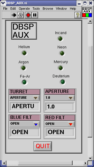
Turret GUI.
The Turret GUI is very easy and intuitive to use. It completely replaces the old blue DBSP control box. At the top are the arc lamp controls. Simply click on the lamp you wish to use. When a lamp is on, the lamp button turns bright green. You may have as many lamps on as you want. The Deuterium and Fe-Ar lamps will turn orange while warming up and then turn bright green when lit. Please remember to click off the arclamps when they are not needed. They have limited lifetimes and are not trivial to replace.
Below the lamps are the four pull down menus that control the aperture, the red side filters, the blue side filters, and the Turret optical path. To make a change simply pull down a menu with the mouse and select by putting the mouse over the menu item and letting go. The aperture and filter selections are listed above. The Turret choices require a little more explanation. The actual Turret is a disk that moves mirrors around above DBSP. The purpose of the Turret is to give the observer a way to change the optical path so that they can view the science target (aperture), the arclamps (lamps), a wider target field (sky), and nothing (closed). By selecting "aperture," the observer will be observing the slit in the slitview camera. By selecting "arclamps," the observer will be sending calibration light down the DBSP slit. Selecting "sky" will give a wider field of view to slitview camera. This option might be useful for TOO obsevations, or to help identify the proper field when the aperture field is too small. The closed position is never used.
If for some reason the Turret GUI freezes or locks up, click the red QUIT button at the bottom of the GUI. To restart the Turret GUI, double click the "launch_auxmon_GUI" icon on the desktop and the Turret should come back up. Ask the support astronomer or telescope operator for help if there is strange Turret GUI behavior.
3. DBSP Auxiliary GUIs (afternoon of the first night)
3.a. Binning and Region of Interest (ROI)
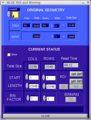
Binning and region of interest.
This window allows you to select any single Region of Interest (ROI) on the chip and/or change the x and/or y binning factor. As in the Main GUI, it has light blue on the status area, and dark blue on the control area.
Original Geometry
The upper part shows the geometry of the array, where Pres:
prescan pixels. Data: Data area of the CCD. Overs: overscan
pixels. amps: total amplifier on the X or Y direction. Total
Size: shows the total size that the image would have if using
full size, calculated as (Pres + Data + Overs) * amps, in the X
direction. (Data) * amps in Y direction (no prescan or overscan area
is used on Y).
Readmode: The upper left yellow square is actually a control. It shows the currently selected read mode, and by clicking on it the mode can be changed. The BLUE side supports left (shown on the image), right, or lowerboth (right and left) amplifiers. The RED side only supports left amplifier.
Current Status
Shows the current status of the geometry, and allows (bottom part) to change it. Note that Prescan and Overscan size cannot be changed from the GUI, and that's why on the bottom area the Total Size stated for both columns (X) and rows (Y) corresponds only to the Data area. Read Time: Shows the total read time for the currently selected geometry. The calculation includes ROI, binning and readmode. show: If selected it will show, on the correspondent Real Time Display the ROI selected, as a blue (BLUE side) or red (RED side) thick line. This is just a quick guidance to the area that has been chosen.
ROI START COLS and ROWS:
starting pixel in x and y
coordinates. The lower left corner corresponds to pixel (1,1).
LENGHT COLS and ROWS: total size on X and Y. The image area of
the ROI will be then: [Xstart, Ystart: (Xstart+Xlen), (Ystart+Ylen)].
OK: go select the chosen area. full: selects the whole
CCD as ROI (full frame). This is equivalent to enter manually the
full frame values.
The system can be set to start with a pre-selected ROI. For handling this, there are two buttons: set def: Use the currently selected ROI as the default, starting value. If this is done, the next time the system starts it will start with this ROI as a pre-selected value, and the next time the get default button is used it will restore to these values. get def: if a change was made, this button will restore the pre-selected default value.
BIN FACTOR: Changes the binning factor on X and Y. OK: go change the binning.
The BLUE side has arbitrary binning factors for every direction (X and Y).
The RED side has only some allowed combinations (X, Y): (1,1) , (1,2) , (1,3) , (2,1), (2,2), (2,3) , (3,1), (3,2).
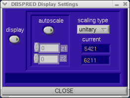
Display settings.
display: enables or disables the Real Time Display. If enabled, it will display the image while it is being read (in "Real Time"). If it is disabled, the image will not be displayed automatically. The rest of the buttons will be disabled only if display is enabled. autoscale: If enabled, the RTD will select automatically the upper and lower values to be mapped. If disabled, the user can enter the desired values (z1 as the lower, z2 as the upper) for the display mapping. z1, z2: the user-selected values for the mapping. These fields will be enabled only if autoscale is disabled. scaling type: type of scaling desired. It can be: unitary, logarithmic or linear (usual). current: these are status only. They will show the current z1 and z2 being used for the mapping. If autoscale is enabled, they will show the values auto-selected on the display, if autoscale is disabled, they will show the use-selected values on the z1 and z2 controls. For first time users don't worry too much about manipulating the Real time Display, it's pretty much stand alone.
3.b. Custom Image Headers
This window allows the users to add/delete/edit any "custom" keyword for the image FITS headers.
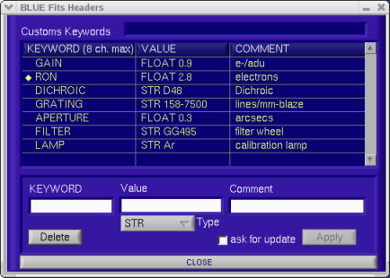
Headers GUI.
The table shows the current custom keywords. Any of those can be changed or deleted, or new ones can be added. If the user selects a line with the mouse, it will automatically fill the fields on the controls (see below) with that values. This values can be entered manually also.
Below the table there are 3 string fields, and 1 Type control. KEYWORD: the name of the desired keyword. Value: the value for the desired keyword. If the type is not specified, it will assume type string. Type: here the type can be selected. STR: String. U8: unsigned 8 bits. I8: signed 8 bits. U16: unsigned 16 bits. I16: signed 16 bits. U32: unsigned 32 bits. I32: signed 32 bits. FLOAT: 32 bits floating point. Comment: comment to appear on the comment area of the keyword header.
Then, there are two buttons. Delete: It will delete the specified KEYWORD. If no keyword with that name is found, it will have no effect. Apply: apply the changes. If the specified keyword does already exists, it will modify it with the new values (specified in the Value and Comment controls). If the specified keyword does not exists, then it will be added. After the changes are made, those keywords will become "default", in the sense that the system will start with those values everytime afterwards (the changes are actually stored in a header's template file).
ask for update: NOT CURRENTLY IN USE.
3.c. Detector Temperature
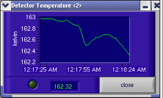
Detector temperature.
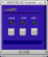
Lamps GUI.
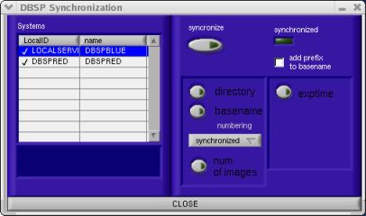
Sync GUI.
This small window is only for monitoring the detector temperature purposes. It is generally left on next to the Main GUI so that the Palomar staff can log dewar temperature with LN2 fills. If it annoys you, close it.
If the temperature falls outside the allowed limits (usually around [150,170] Kelvins), the trace will turn red, and the LED will blink. This serves only as an alarm. If you see this happen, notify somebody on the Palomar staff. The window updates every 60 seconds, so if you are restarting the system, you may see blinking lights or the wrong colors for a minute.
3.d. Lamp Controller
This window controls the Prime Focus dome lamps.
The HIGH and LOW lamps are flatfield lamps that project from Prime Focus up to a painted square on the dome when the telescope is pointed to the zenith. The ARC lamp is a mercury line standard lamp which was installed for the COSMIC spectrographic multi-aperture mode. COSMIC has no internal calibration lamps. Most DBSP users use the internal wavelength calibration lamps and not the dome ARC lamp.
Operation is simple, push the button with the mouse and the lamp goes on. To turn off a lamp, toggle the button again with the mouse. The display box below the lamp buttons, give the "on" status.
3.e. Synchronization Interface (Blue side only)
NOTE: The RED and BLUE cameras are now running on separate computers, and the sync function no longer works.
This window is particular to the BLUE side, which acts as a "master" when the system is run synchronized. For more information on this please read the general explanation.
This window allows you to synchronize or un-synchronize both RED and BLUE sides. And to set what the user wants to be synchronized. The Systems table on the left of the GUI shows what systems are available. For DBSP there are only two systems: DBSPBLUE and DBSPRED (for BLUE and RED sides respectively). On the right side there are the actual controls for this GUI.
synchronize: If enabled, both systems are synchronized. If disabled, both system are un-synchronized, which means that both sides can be run as totally independent systems. When the systems are synchronized, the synchronized LED will turn green, and a check mark will appear in front of the DBSPRED entry on the table.
The rest of the controls are enabled only if synchronize is enabled. The fact that the systems are synchronized implies this aspects:
- Shutter open: shutter will be opened at the same time (BLUE GO button).
- Exposure will be Paused/Resumed/Aborted/Stopped on both sides (BLUE Pause/Resume, Abort and STOP NOW buttons).
- Sequence will be stopped at both sides (BLUE STOP after current image button)
- Object and observer will be the same on both sides (specified on the BLUE object and observer controls)
Besides these basic aspects, there are some other parameters than
can be synchronized if desired. This is the usage of the rest of the
controls on this GUI. add prefix to basename: If checked, it
will add a prefix to the images of both sides (b_ for BLUE side, and
r_ for RED side), so now the final image name will appear as
<prefix><basename><image_number>). directory: If
ON, both images will be written on the directory specified on the
BLUE GUI (image path control). basename: If ON, both images
will have the same basename (BLUE basename control). numbering: synchronized: the image number will be the same for both sides
(BLUE image number control), unsynchronized: numbering is kept
independent for both systems. num of images: If ON, the number
of images of the sequence will be the same for both, set by the BLUE
number of images control. exptime: If ON, the exposure time
for both sides will be the same (BLUE exptime control).
4. Important Notes
- If directory, basename and numbering are all synchronized, the system will check automatically add prefix to basename in order to avoid the images to override each other. In this case the images will be written as:
- If directory and basename are synchronized, but numbering is unsynchronized, it is the responsibility of the user either to check adding the prefix, or to keep the numbering distinct enough to avoid confusion.
BLUE image: <image path>/b_<basename><image_number>
RED image: <image path>/r_<basename><image_number>
Obtain test frames (to see where spectrum hits the chip & set your chip readout area on the ROI GUI, see the ROI section).
Perform the following procedure for each camera in use:
- Turn on the appropriate toggle switch on the box labeled COMPARISON LAMPS on the DBSP control box: He, Ne, Ar are generally good for the red side, hollow cathode (Fe-Ar) for the blue, Hg or He if you want only a few lines; an incandescent lamp may be used for flats, but most observers prefer dome flats. Most lamps take just a few seconds to warm up, but the hollow cathode (Fe-Ar) lamp takes 20 or 30 seconds. It's OK to leave lamps on for 10 minutes or so, but not for an hour.
- To view these internal lamps, select SKY with the rotary switch on the control rack sitting on the guider desk [in SKY mode, the on-axis guide camera directly views the sky, and the pickoff mirror blocks sky light or outside light from reaching the spectrograph, but allows viewing of internal comparison lamps; in SLIT mode, the on-axis guide camera views the sky in reflection from the polished plates of the slit].
- Make a single-camera CCD exposure by With 1200 l/mm gratings, typical exposures are 1 sec. on the blue side (more for the Fe-Ar ~20 sec.) and 3 sec. on the red.
- Check that bias levels (dark intensity) are about 5500 counts for the Red camera CCD21, and 3000 for the Blue CCD23.
- Move the cursor to the edges of the usable field to be retained when you trim the display, and write these coordinates down because they will be inputs to the ROI GUI. Grating changes move the spectrum around on the chip. Take some images, and apply the desired ROI changes, and take some more images. Remember that the smaller the area read out, the shorter the read time.
5. Setup Tasks: Focus, Flats, Bias (afternoon of every night)
NOTE that the following #1, #2, and #3, should already be done by the Palomar staff. If you have a concern contact the day crew or support astronomer. Please do not make any changes without help.
- Examine spectra to see that the images of the slit form vertical lines on the screen. If you find that the blue camera has slit images turned clockwise, then turn the dewar in its mount (counter)clockwise to correct; if the red camera slit images are turned clockwise, turn the dewar (counter)clockwise in its mount.
- Check that the center wavelength is on the center pixel or the tolerance you require; otherwise, tweak the gratings. Don't forget to use the additional numbers provided by the grating angle calculator to verify that the spectrum has the correct dispersion, etc.
- Check the focal adjustment on the red side; set it as a function of ambient (dome) temperature by following the instructions taped to the side of the DBSP instrument. Be careful not to grasp the indicator dial while adjusting, as it is held by only a set-screw—there is very little backlash in this adjustment, but it is probably best to approach from the same direction (lower numbers) each time.
- Check the focal settings of the two collimators: arc-lamp images with a 0.5″ slit should give ~ 3.0 pixel FWHM on the blue side, and ~< 2.7 pixel FWHM on the red. Also it is important to note that the red camera is a lensed system. For the low dispersion (158,316) gratings there is significant focus error associated with wavelength. For example, if you focus in the center of the 158 ln/mm grating, you can expect a focus FWHM in the center of the chip ~1.5 pixels but see 4 or 5 pixels at the extreme red and blue end of the CCD.
- Take BIAS frames. In the Main GUI set the exptime to 0, set the obs. type to bias, set the basename and comments to whatever you like, and take 10 or so biases.
- If you like to take DARK frames, set the exptime to desired value, set the obs. type to dark, set the basename and comments to whatever you like, and take as many as you need.
- Take FLATS (flatfielding frames)—either TWILIGHT FLATS on the evening sky or DOME FLATS after the lights are turned out in the dome at 3 or 4 PM. Twilight flats are a bit tricky to get a decent number of counts, and must be done just as the sun sets to get the blue side right. Dome flats involve pointing the telescope to an illuminated spot on the dome, opening the mirror cover, and exposing. Note that dome flats can have an emission line around 6708 Å, which, when used in data reduction, can create a spurious absorption line at 6708 Å in spectra. Flats may also be done using the internal incandescent lamp (not recommended) and following the procedures outlined below for obtaining comparison lamp spectra.
- make sure lights are out in the dome;
- have telescope operator or crew point the telescope at the illuminated patch at the zenith used for dome flats;
- open mirror cover using switch at telescope operator's console;
- open the Lamps GUI, select HIGH to turn on the high-intensity dome-flat lamp (select LOW to turn on the fainter flat-field lamp; select OFF to turn off all lamps);
- on the Turret GUI pull down the turret menu and select aperture allowing light through the slit;
- set the exptime, obs. type, basename and comments, and take an exposure;
- take a few short exposures to calculate a desirable number of counts (remember the shutter is unreliable under 1 second, the red side saturates ~40k, and the blue at ~65k);
- to take a series of exposures, enter your value into the number of exposures box;
- remember to select OFF in the Lamps GUI when you're done;
- make sure telescope mirror cover is closed.
Note: a quantitative approach is effective—derive the tangent of the offending angle by the ratio of x-pixels offset to y-pixel range seen on the display unit, and match this with a correcting angle whose tangent is the amount of travel of the dewar-rotating micrometer, divided by the 4-inch radius at which this micrometer is mounted. Or just take images and make moves until you get it right.
Calculator caveat: the resolving power returned by the calculator uses resolution per pixel, not per slitwidth like the other quantities given (hence this resolving power does not change with slit choice).
The collimators have lots of hysteresis ("backlash"), perhaps 10 units, so be sure to approach any given setting from the same direction each time (from lower numbers, by editorial fiat)— In practice, spectra are fairly insensitive to collimator focus, and the optimum range is fairly broad. The following table nonetheless provides a rough guide. If you are alone, focusing means running up and down the ladder to make adjustments in the Cass cage. The support astronomer will be happy to adjust the collimator focus while you take focus images.
| Collimator Focus (1 digit = 1905 mm) [a] | ||
|---|---|---|
| Collimator | Blue | Red |
| Focus for parallel light | 450 | 750 |
| Focus for good optical performance | 390 – 510 | 690 – 810 |
| Total focus range | 250 – 600 | 690 – 1070 |
| [a] larger numbers move image plane further from telescope | ||
TAKING DOME FLATS (the popular choice): Please ask for help the first time you do this.
6. Taking Data on the Telescope: Focus, Flux, Standards
- Tell the telescope operator the desired "ring angle"—the orientation (position angle) of the slit on the sky, in degrees east of north.
- Focus the telescope on a star (you will need to repeat this once or twice during the early evening as the temperature changes. The telescope operator will perform this for you):
- Make sure the Turret is at aperture (this allows the center field camera to view the slit and surrounding field stars reflected from the slit blades, and lets telescope light into the spectrograph);
- Use the hand paddle to adjust telescope focus until stars in guide camera field appear sharp (guide camera and DBSP are parfocal); there is a readout of telescope focus in mm on the RA, DEC display screen; OR there is a automated focus box on the FLI camera GUI. Ask the telescope operator to give you a demonstration.
- If you are doing spectrophotometry the telescope operator can call up a suitable source from a computerized list of spectrophotometric standards compiled by Gunn. You may wish to do two or more standards during the night, particularly if accurate flux calibration is important to your experiment. There is also a standards GUI that can be run for all 200-inch cameras.
7. Taking Data on the Telescope: Science Object
Download the DBSP Log Sheet.
- If you need to, take comparison lamp for wavelength calibration before (and after) any exposure on the science object:
- Select "lamps" on the Turret GUI.
- Turn on the desired lamps by clicking on the corresponding buttons. Fe-Ar is good for Blue, He, Ne, and Ar, are good for Red—Fe-Ar takes about 30 seconds to warm up; neon, just a few seconds.
- Take an exposure; use about 30 seconds for Blue, 1 second for Red.
- Turn off the comparison lamp (don't leave it on for hours).
- Select aperture again on the Turret GUI turret menu, to prepare for object exposure.
- As mentioned above use IRAF and DS9 to display your images.
- Set up the guider (consult telescope operator and guider appendix);
- Observe your science object:
- set the ring to the desired position angle for the slit on the sky, measured E of N.
- put your position reference star (from which you will offset to your science source) onto the center of the slit and have the telescope operator "X" the coordinates.
- put the cursor on the slit center as well.
- ask the telescope operator to offset to science object.
- fill in the desired header, exptime, obs. type, basename and comments information, and take an image.
- use the pause or stop buttons in the Main GUI to alter exposures or sequences, see above #6 in Main GUI.
- Take comparison lamps if you need precise wavelength calibration after this exposure on the science object (repeat steps 1.a to 1.f at top of this section, as were done before science exposure).
- Repeat the larger cycle of major steps 1 to 5 for each source position.
8. Data Transfer / Media Backup (end of the run)
Your files are saved to /rdata/DBSP on the DBSP computer.
Sftp file transfer can be easily done from this location.
See the support astronomers for relevant passwords and paths.
There are DVD burners on each of the control room workstations. They are easy to use "drag and drop" burners. Ask for help the first time you use them, and take notes. You are responsible to supply your own media (DVD, -R, -RW, etc.).
9. Appendix: Brief Primer on Guiders
The Autoguider has comprehensive documentation of its own (see Palomar Autoguider); we summarize the main points here.
The telescope operator and support astronomer can help you with the finer points and getting set up. Some observers prefer to have the telescope operator run the guider. The choice is up to you, but don't hesitate to ask for help if you get stuck using the guider. BE CAREFUL, the guider cameras are image intensified, and can be damaged with over-exposure. The main controls that you will use are:
- ENABLE button at upper right—turns on the guider; clicking on it (with left button of mouse) toggles it ON/OFF, and it changes color accordingly—yellow means it's OFF (i.e. caution, you're not guiding).
- INTENSIFIER GAIN slidebar, 1/3 of the way down on right side—turn it down (via click-and-drag to left) when slewing, as you would to protect any camera.
- FRAMES PER INTEGRATION and INTEGRATIONS TO AVERAGE slidebars, about 1/2 way down on right side—the product of these is the number of (30 Hertz) frames that are averaged in each update of the display; you might adjust these according to seeing and brightness of the guide star.
Most of the many other controls may be ignored and left the way you found them, or the telescope operator advised you to set them. The on-screen green box within which the guide star position is calculated (by, eg., a centroid) may be resized by clicking and dragging on its edges. The crosshairs inside the box display the current position solutions in x and y; the crosshairs outside the box disappear when the solution is not found.
Questions? We've answered many common observing and operations questions in our observer FAQ page.
Please share your feedback on this page or any other Palomar topic at the
COO Feedback portal.
DBSP Cookbook / v 2.1.1
Last updated: 15 March 2019 CMH/ACM
|
|
|