
|
|
|
Palomar High Angular Resolution Observer (PHARO) Cookbook
View the original cookbook.
This Cookbook gives a step-by-step guide to operation of PHARO at
the Palomar 200-inch Telescope. For a description of the instrument
and information needed for advance planning of an observing run, go
back to the PALAO
homepage and click on the Overview button. As of this update (2008)
an observing run with AO divides the labor in the following way. The
telescope operator is responsible for the telescope and Natural Guide
Star (NGS) operation. A visiting engineer is responsible for the
Laser Guide Star (LGS) system. The observer is responsible for, in
this case, the PHARO the science camera. Use the web pages as an
introduction, and the support engineer will give you instruction on
the system to fill in the blanks for PHARO when you get to Palomar.
The AO manual is intended as a reference for AO operation, and may be
read by observers interested. However the observer’s responsibility
is PHARO.
Despite its intended real-time usefulness, the Cookbook contains nuggets of instrument theory here and there that might require some time to digest... so of course a thorough reading in advance of the observing run is recommended to avoid unpleasant surprises at the telescope. (Failing this, telescope operators carry extra Kleenex).
- One-time setup tasks
- Start-up and GUI
- Science camera primer
- Operation
- Summary of imaging mode
- Imaging, exposing, nodding, dithering, & macros
- Coronagraphy
- Grism spectroscopy
- End of the night
- End of the run
- Preliminary data reduction steps
Contents
1. One-Time Setup Tasks (afternoon of the first night)
- Get to the telescope no later than 2:00 pm on the afternoon of your first night to make contact with the set-up crew, and the support engineer. The set-up crew goes off at 4pm, and the support engineer is on from noon to 10pm. The support engineers share an office just off the control room for the 200-inch.
- The PHARO computer is Ezra3. Ezra3 is the new linux replacement for the old Ezra2 sparc station (thanks Tom Hayward!).
- The day crew will handle all liquid nitrogen fills for the PHARO dewar. The PHARO dewar holds for 24 hours. If you are interested, ask one of the daycrew to show you how to check PHARO's temperature. This is a quick and simple way to check that the dewar is holding.
- Control is the AO control computer. The daycrew may already have this up and running when you arrive.
- Initial system alignment and checkout tasks will be carried out by the support engineer, and are listed in the palaosetup html. Go to PALAOSETUP if you are interested...
- Aligning the pupil and determining the centroid offsets, are also undertaken by the support engineer in the afternoon. These tasks are very important for optimzing the AO correction. If there is time, it useful (but not critical) to see how this is done.
- An excellent time to review the PHARO GUI is after the system is tuned up, and before you go to dinner. Have the support engineer show you all the PHARO functions. Controls include; camera, dithering, filters, slits, apertures, masks, nods, image diagnostics, and error display. All these will be covered below. There is also the link to the Cornell PHARO page on the PALAO homepage.
- Obtain (PHARO) dark(s): use the internal PHARO dewar block...i.e., set the Lyot filter wheel to BLOCK. It's best to have darks for each integration time you plan to use during the run. Take a few to be safe and perhaps to allow median filtering. Then go to dinner.
2. Start-Up and GUI
2.a. (Normal) Start-Up
- Open a terminal and check disk space is adequate via
df
            -k
command; if not, ask the support astronomer for help. - AO should be up and running before you start PHARO (or else restart PHARO later) to get proper communication with TCS and hence proper display of telescope quantities (RA, Dec, etc) in the window at lower left on PHARO's screen. Check with the support engineer for information on AO current status.
- Run the program via
xpharoon a terminal window prompt. You will be prompted for the subdirectory into which data should be written, and the names of the observers. - You are pretty much free to crash and restart
xPHAROany time; you'll just lose a couple of setups on the PHARO screen (e.g. the green crosshairs; the display settings). You should have the Lyot wheel BLOCKED before you crash/reenter, for safety. - Inspect the small message window that shows beneath the
PHARO GUI...be sure that current telescope positions are being
displayed, instead of just zeroes, and exit/reenter
xPHAROif there's a problem. - Take a "quick" image or two (not saved to disk)...even with Lyot wheel blocked, you should see a little dark-image structure.
2.b. GUI and Display Screens
The Left Monitor
Here is a snapshot of the left monitor on Ezra3. After you
start xPHARO and fill in the data path pop-up, this is what you
will see.

Left monitor.
- The lower left window is the xPHARO camera GUI. In this window you will control exposures, filters, grisms, apertures, fields of view, and macros. At the bottom of this window is an ever changing camera status window. This is the single most important window, there will be much more to say about this GUI which is actually an analog layout of the PHARO optical path.
- The xPHARO plot window is an excellent tool for determining image quality. Used in conjunction with the tools in the xPHARO display window, xPHARO plot can give information on image Strehl, uncorrected seeing, and corrected PSF/FWHM.
- The right side window is the xPHARO display window. This window gives detailed information on the entire PHARO image with its capability to "zoom in" on observer designated features.
- As mentioned in item #1, there will be more to say about each of these windows. It is also wise to look at the PHARO manual, which has a link on the PALAO homepage.
The Right Monitor
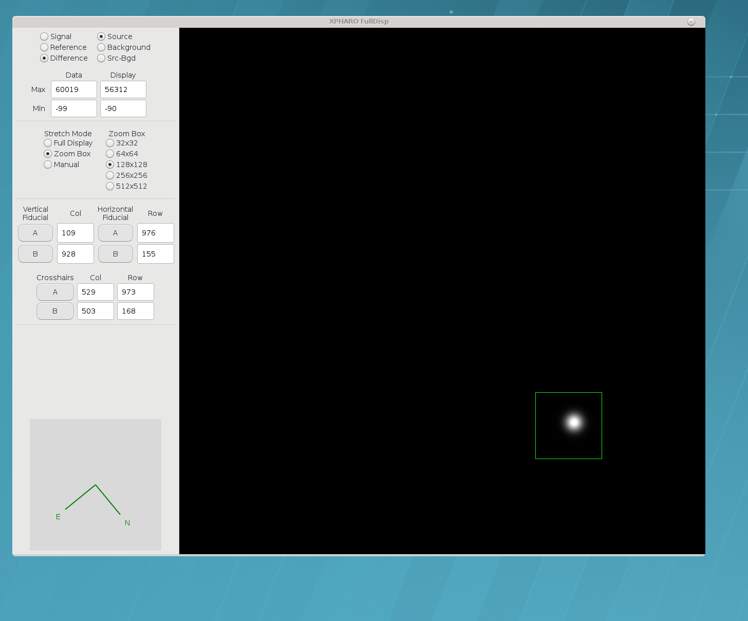
Right Monitor.
- This monitor display contains the full 4 quadrant PHARO image.
- On the left are 4 display and control areas.
- At the top is a display that shows the type of image (eg. Reference), what buffer is being displayed (eg. Background), the image max/min, the green box max/min, and the green box stretch mode (eg. Zoom Box).
- The next box down selects the size in pixels of the green zoom box displayed on the PHARO image (eg. 128 × 128).
- The next box down selects green crosshairs and lines that are used to mark slits, spots, and target positions. Simply click on A or B and a crosshair or line will appear on screen. To move the fiducial markers around, all you need to do is click and drag. The Col and Row indicators display marker column and row pixel position on the image.
- The final box at the bottom indicates cardinal image direction.
A section will be added to this document at a later datewhich goes into more detail on GUI selections, but for the moment refer to the above images when this text refers to GUI commands. Also check the PALAO link to the Cornell PHARO manual.
2.c. Flats
Obtain (sky or dome) PHARO flats for each filter/platescale combo you'll use. For sky flats:
- Use the chart of detector counts vs. time (after sunset)/(before sunrise), found in the blue PHARO manual, as a check. You'll have to be set up on the sky (PALAO on, open to sky, just a flat DM) monitoring counts at least 15 minutes before sunset for broadband (J,H,K,K',Ks); narrowband require being on an hour or two earlier (check with crew regarding the rules of telescope/G-star proximity)
- Work fast; suitable sky brightness lasts only 20 or 30 minutes.
- Cycle through the suite of filters you'll do science with.
- For each filter, get about 5 different 10-second exposures that span a good range (a few tens of thousands) of counts as the sun rises/sets. For flats through neutral-density filters, you may have to make do with fewer counts.
- Point the telescope at zenith and let Earth's rotation smear out any stray stars in your way.
- Remember that narrow-band filters may need to be done well before sunset or after sunrise, and at longer integration times, to get enough counts, brighter sky is preferable to longer integration to get the counts (to avoid those stray stars).
Flats are generally believed to be constant over an observing run, so long as nothing in the optical setup is changed.
2.d. Pointing, Focus, Seeing
- Once you are ready do some science, the telescope operator will want to look at an SAO star near zenith to check and set up several things. The telescope operator will want to check pointing, get a rough focus, and get an uncorrected seeing value from PHARO. To get the uncorrected seeing expose on the SAO star for 30 to 60 seconds with no AO correction. The support engineer will show you the tools for estimating the seeing on the PHARO GUI.
- When you are done with the SAO star set the Lyot wheel to Block. It is required that the observer do this before every telescope slew.
3. Science Camera Primer
After the PALAO console has been used to achieve a good lock on the new guide/target star, most of the action occurs at the PHARO console. Small (5″) closed-loop dithers and even locking/unlocking the loops can be done remotely from PHARO.
3.a. Safety Rules
- Be patient, the PHARO GUI will only accept one command at a time, and that command must complete before initiating anything new. If you try to make a new command before a previous command has finished, you will get an annoying error message.
- DO NOT MOVE THE Shutter (located in the middle of the PHARO GUI)...just leave it open. It could get stuck in the closed position if moved, requiring days to fix.
- ALWAYS Block PHARO's internal Lyot stop during large telescope moves to avoid frying science CCD.
- Turn off Continuous Acquisition (Cont Acq) mode before taking an image or moving a motor.
- Be very careful when using the tweak option on a motor's pull down menu. It is possible to overwrite the motor position default calibration file. It is better to home the motor and try the move again. Putting the Carousel wheel in pupil mode can help determine if a wheel has not moved correctly. Ask the support engineer to give you an in depth education on the tweak function, and its pitfalls.
- Make small (no more than 5 arcsecond) dithers of the telescope while loops are locked (not really for safety, but to keep tip/tilt and SSM mirrors happy and loops locked).
3.b. Philosophy
- There are two set of image buffers: "regular" and quick, you take an image into one or the other with the upper/lower rows of image-taking buttons, and you may choose their integration times independently in the white rectangles immediately above those. ["Regular" is not called that...it is the row Take Src & Write Diff etc].
- Quick is always a single image, and not written to disk. You use it to scout out the situation, perhaps to check the field or exposure time. "Regular" will take as many images as you choose in the #Cycles box, and write them all to disk. Use this option for your science observing.
- Within those divisions, there are two more kinds of image buffers: source/background...these are addressed with the left/right columns of image-taking buttons, and are referred to in the display window as Src and Bgd. If you obtain a background on dark sky, you may display the more sensitive background-subtracted difference.
- Any image, regular or quick, source or background, is made up of two readouts of the CCD chip, called "signal" and "reference". Except in engineering modes, you will generally want to work only with the "difference" of these.
4. Operation
4.a. Summary of Imaging Mode
REMEMBER: for objects fainter than about 10th mag at V (current limit of PALAO's acquisition camera), PHARO's continuous-acquisition imaging mode is a powerful acquisition tool ...and it has a wider field of view than PALAO's acquisition camera...
- At start of setup, make sure Lyot wheel is set to Block (as with most selections, a pull-down menu option).
- Select plate scale (25 mas or 40 mas pixels) by selecting 25/40 arcsec field on Slit wheel, and 25/40 mas on Carousel.
- Select spectral and (optionally) neutral-density filters from the assortment offered on the Filter and Grism wheels.
- The Shutter wheel should be set to open
(DON'T MESS WITH IT...it may get stuck).
The shutter is intended for future automated use with the Laser guide star upgrade. - Enter an integration time, in milliseconds, in the Quick Time box (2000 = 2 seconds is the shortest for the full array)...the box will alter it slightly while accepting it, to fit chip readout specs.
- When setup is all ready, move the Lyot wheel to the setting of choice, most likely Standard Cross, which has the basic pupil-plane (Lyot) mask designed to cover the aperture and spiders of the telescope.
- Hit the Quick Src button, and in a few seconds an image should be displayed.
- Hit the Cont Acq button if you wish, to continually obtain new images (none saved); remember to press it again to exit before doing other things.
For more information download the PDF Cornell PHARO manuals at ftp://ao.jpl.nasa.gov/PHARO_ops.pdf and ftp://ao.jpl.nasa.gov/PHARO_setup.pdf. To be honest these manuals are preliminary, more PHARO information will become available on this web page.
4.b. Imaging, Exposing, Nodding, Dithering, & Macros
- The PHARO array is a four quadrant HgCdTe chip, where each chip is 512 × 512. The CCD optimum linearity is up to 40,000 counts.
- PHARO pixels are readout one row at a time. Then a reset is applied to all the pixels in the row. A timing discontinuity exists on chip quadrant borders, so it is wise not to put targets on the borders.
- On long dark exposures, you will notice a circular glow at the four quadrant read points. This is multiplexer FET glow, which increases with exposure time.
- There is no shutter on this array. When idle, the array continuously clocks and resets to a preset bias level. It is always recommended that the block on the Lyot wheel be inserted into the path when slewing the telescope, or when PHARO will be idle for a significant length of time (THIS IS YOUR 4th WARNING).
- The bias reset is noisy. Correlated double sampling is the technique used to remove reset noise.
- The default PHARO image setup sends a difference image to the display. This image is the difference of the target signal minus the initial reference signal.
- All exposures are sent to either the source (src) or background (bgd) buffer. Quick exposures are for target acquisition, exposure determination, and AO peaking. Quick exposures are not saved to disk, unless the write FITS button is pushed. Take & Write exposures are written to disk as standard three dimensional FITS files (X, Y, quadrant#). No coadding, or image subtraction is done to the images before writing to disk. The S-B display button on the GUI DOES NOT create a subtracted file of the source minus background files. The displayed subtracted image is for display only, unless you use the write FITS button.
- Clicking the Detector Setup button opens up the "Settings" popup window. In the popup, the quadrant size can be changed, endpoints can be added, and what gets saved to file can be expanded. There are no binning options on PHARO.
- The #Cycles text box is used to enter the number of "Quick" or "Take & Write" exposures to be taken in sequence with on button push.
- The xPHARO display box can be used to get various image, zoom modes, stretch options, Strehl analysis, photometry statistics, statistical plots, and full field options. Some of these were covered earlier in this document. To prevent overloading the new observer with more detail on these options, it would be better if the observer meets with a support engineer to go over the entire PHARO GUI in general, and the display options in particular.
- Dithering is accomplished with two steering mirrors in the AO bench. These mirrors moving in tandem enable the AO system to remain locked on a target while the target can be dithered in the field of the science camera. Here are some tips for "smart" dithering: Don't make dither moves greater than 5 arcseconds, and wait 2 seconds before making another move to maintain a stable lock. Moves are made manually, or with a macro, both methods are discussed in this section.
- If the observer makes a dither move too far or too fast, the AO system will lose lock. The telescope operator will need several minutes to restore the lock.
- On the xPHARO GUI there are manual dithering buttons for the observer to use. The buttons can move in either sky or detector units. As stated previously, the buttons move the steering mirrors to move the target on the PHARO array but not off the AO wave front sensor (dithering). The steering mirror motors suffer from hysteresis, and stiction. Fine move accuracy in a best case scenario is around 1 pixel/.025″. These buttons are mainly used to get fine placement behind a coronagraphic spot, or a grism slit.
- A digital fine move method exists. This method applies tip/tilt to the deformable mirror. This method is controlled by the AO/telescope operator. The digital moves are once again a method to make fine moves to position a target on a coronagraphic spot or slit. While this method is accurate, it is limited in range 0.2″, it reduces Strehl by several percent, and it reduces available DM stroke.
- There are three nodding methods to move the telescope with the AO unlocked (open loop). Nodding is used to make moves for sky frames, field identification, and star searching. The three choices are: 1) telescope hand paddle, 2) ask the telescope operator to move the telescope with the TCS, 3) use the xPHARO mover buttons with the system unlocked (be sure to unlock).
- Macros are simple text files that can make dither moves,
take exposures, move filter wheels, and repeat sequences. Examples
of macros can be found on the PHARO computer Ezra3 one level below
the PHARO login directory at
/macros. Macros are loaded with the Load Macro button on the xPHARO GUI. Macros are run with the (you guessed it) Run Macro button. Be sure to add 5 second pauses after each 5 arcsecond dither move, to make sure the steering mirrors are stable.
4.c. Coronagraphy
- The slit wheel holds the two coronagraphic spots. The slit wheel is in focus, and the spot locations can be easily identified against a moderately bright background.
- The coronographic spots are mounted on transparent calcium fluoride substrate. The substrate is masked to match the 25″ field. There is no wider field of view advantage in using the 40″ field since the area beyond the 25″ field substrate is opaque.
- The two spots are 0.46″ and 0.91″. They can be selected using the slit wheel pull down menu.
- A drawback to coronagraphy is the fact that the slit wheel is not repeatable to better than a few pixels. Dust specks and the spots will not line up on the same locations after slit wheel moves. This non-repeatability makes flat-fielding a problem. There are two choices for taking flats; 1) remove the coronagraphic spots for flats (use the 25″ field mask), and 2) set up the slit wheel for one spot selection, and never move the slit wheel after taking flats.
- Note items 11. through 16. in the section above relating to dithering, nodding, and macros. The .025″ move is the finest move that the SSM's can currently make, and this move is unfortunately not always precise with the mover buttons.
- It is reported by observers that the spots are slightly transmissive in the K-band. If the object is bright enough, or the exposure long enough the occulted object should be detectable with the xPHARO line display plot. Use the line display plot to center the target behind the spot. BE CAREFUL to not over expose the array. Use short exposure quick sources to make sure the target is fully behind the spot before taking long science exposures.
- System flexure is an issue. Targets can drift out from behind the spot on the order tens of minutes. The flexure effect is variable depending on Cass ring rotation, altitude, and azimuth.
4.d. Grism Spectroscopy
- In the afternoon home the slit wheel. After homing, move the slit wheel to the desired slit for observations. Take an image with enough stray light to see the slit. Use the vertical fiducials to mark the the slit location. You will need this when observing to put your object correctly on the slit.
- If the the slit does not look vertical, use the tweak option in "current" mode to get to vertical. After tweaking, home the Slit wheel, and then move back to your slit. Take another image to make sure that the slit is vertical. Tweak and repeat as necessary.
- Grism spectroscopy with PHARO was designed for use on the 40″ field. Make sure the Carousel wheel is in the 40″ position.
- In the afternoon, home the Grism wheel, and then move to the grism of choice. Take a test spectra of the dome and check that the spectra is horizontal with the horizontal fiducial markers. If the spectra is not horizontal, tweak in "current" mode, home the wheel, go back to the grism and check the spectra. Tweak and repeat homing as necessary.
- The grism wheel is "heavy" and a bit unbalanced due to the grism wedges. This at times can cause the grism wheel to make incomplete moves. During observing if the spectra looks strange, home the wheel and try again.
- It is a good idea to write down the coordinates of critical fiducial markers. If the xPHARO GUI crashes, and you need to re-start xPHARO, the fiducial locations will be lost.
- The basic spectral observing tactic goes something like... Set the Slit wheel to 40″ field, set the Grism wheel to a safe ND location, make sure the Carousel is at the 40 mas position, and then take a short "quick" image to safely set an exposure value. With the camera in Cont Acq (& AO locked), dither the object into the vertical slit fiducial markers that you have previously set. Turn off Cont Acq, move the Slit wheel from 40″ field to the chosen slit, and take another "quick" image to confirm the target location on the slit. Then move the Grism wheel to the selected grism. Take science images. When slewing to a new location, set the Lyot wheel to Block, set the Slit wheel to 40″ field, and set the Grism wheel to some safe ND location.
- The currently available slits are; 0.13″, 0.26″, 0.52″. The available grisms are; J, H, K bands.
5. End of the Night
- Take twilight flats if desired.
- Block light to the PHARO detector.
- Check if Ezra3's disk is getting full. If so, back up and erase some images.
- It is not recommended to do PHARO backups while observing.
6. End of the Run
- By Palomar custom, you have until the next afternoon to remove your data from Ezra3, the Linux workstation that runs PHARO, and purge the disk for the next user. It never hurts to leave a note on the computer giving its status.
- If yours is the last night of AO, make sure you put a note on Ezra3 for the day crew, telling them that you are still running tape backups or FTP. Hopefully the day crew will gently roll Ezra3 to the corner of the data room without disturbing it.
7. Preliminary Data Reduction Steps
- PHARO data is recorded as standard FITS files, one file for each
PHARO image. The PHARO filename convention is "ph" followed by a
4-digit number, and then
.fits. The first image in a data set isph0000.fits. - For each image the full 1024 × 1024 PHARO array is segmented into four quadrants, and each quadrant written to an independent FITS extension (data object) in the output file, where NAXIS = 3. Put another way, the FITS data is stored as a 512 × 512 × 4 array. Image viewing software such as ds9 may be used to view these four quadrants/extensions independently.
- A matlab code snippet to reassemble PHARO FITS files into a single image is here:
- Some reference material can be found here: https://fits.gsfc.nasa.gov/fits_documentation.html
data = fitsread(filename);

% separate each pharo quadrant into a variable
q1 = data(1:512,1:512,1);
q2 = data(1:512,1:512,2);
q3 = data(1:512,1:512,3);
q4 = data(1:512,1:512,4);

% restitch the quadrants into a 1024 × 1024 image
img(1:512,513:1024)    = d1;
img(1:512,1:512)       = d2;
img(513:1024,1:512)    = d3;
img(513:1024,513:1024) = d4;
https://en.wikipedia.org/wiki/FITS
https://archive.stsci.edu/fits/users_guide/node33.html
Questions? We've answered many common observing and operations questions in our observer FAQ page.
Please share your feedback on this page or any other Palomar topic at the
COO Feedback portal.
PHARO Cookbook / v 2.0.1
Last updated: 31 March 2019 RSB/CMH/ACM
|
|
|